Objective:
In this project we will connect Robot Car to WIFI and Use an APP to control the car through Internet. This is a typical Internet of Things(IoT) Application.
You must complete lesson 5 before you continue on with this lesson.
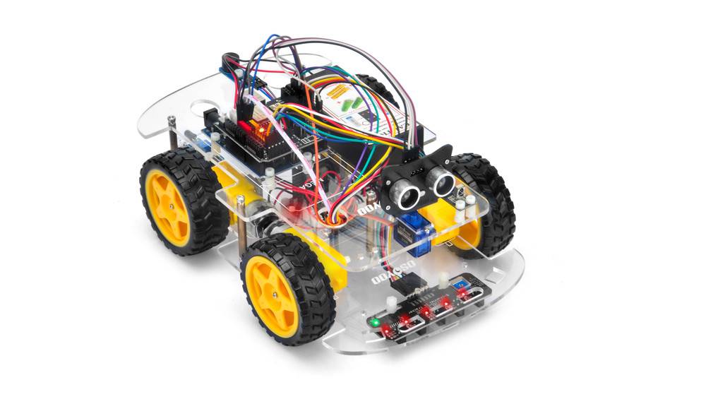
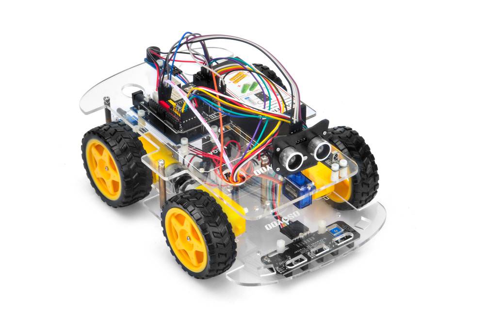
Step 1: Install the smart car basic frame work as per lesson 5. If you don’t install tracking sensor module, please completed installation in Lesson 4.
Note: As the limited Digital signal pins, you need to remove some wires of lesson 2 and lesson3. If you have already completed installation in Lesson 1 , Everything keep it as is except move ENA from D9 to D3(we need D9 for Servo control). If you have installed Lesson 2 or 3, you have to remove the wires.
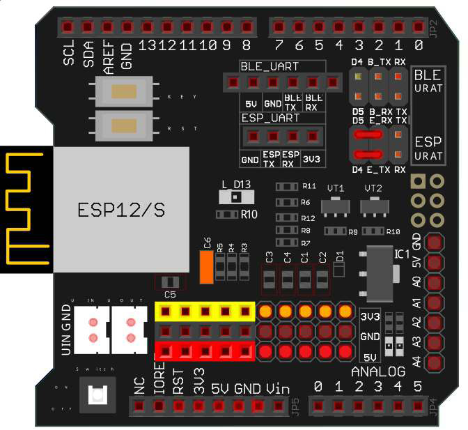
Step 2: Connect E_TX (Esp8266 TX) pin to D4(soft serial RX for UNO) and E_RX(ESP8266_RX) pin to D5(software serial TX for UNO) as per following picture
(Note: Our OSOYOO Uart WiFi shield V1.3 are connected BLE URAT TX/RX ports to D4,D5 with jumper caps by default. If you find the BLE URAT TX/RX ports are connected, you need remove these jumper caps and change to connect ESP URAT E-TX to D4 and E-RX to D5)
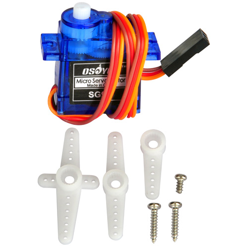
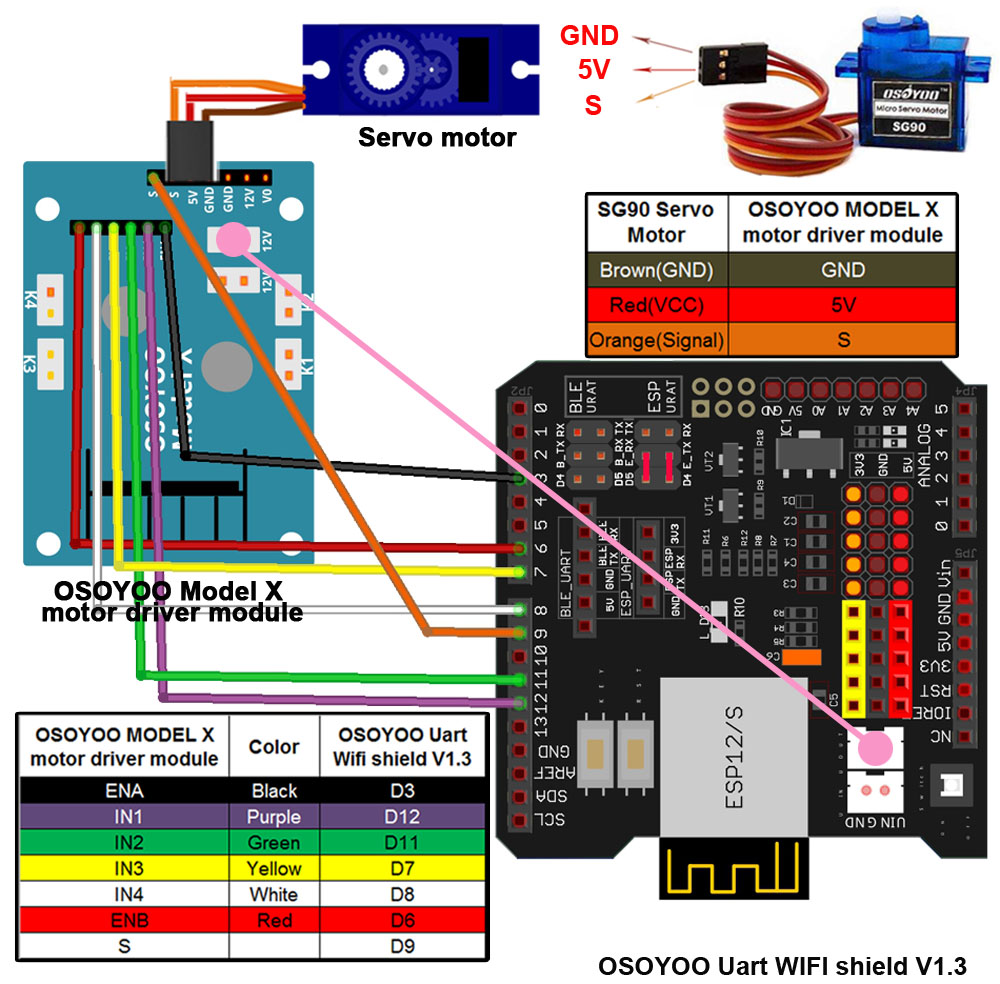
Step 3: Connect SG90 servo motor, OSOYOO MODEL X motor driver module and OSOYOO Uart WiFi shield V1.3 as following graph (If you complete wires in lesson 5, please skip this step):
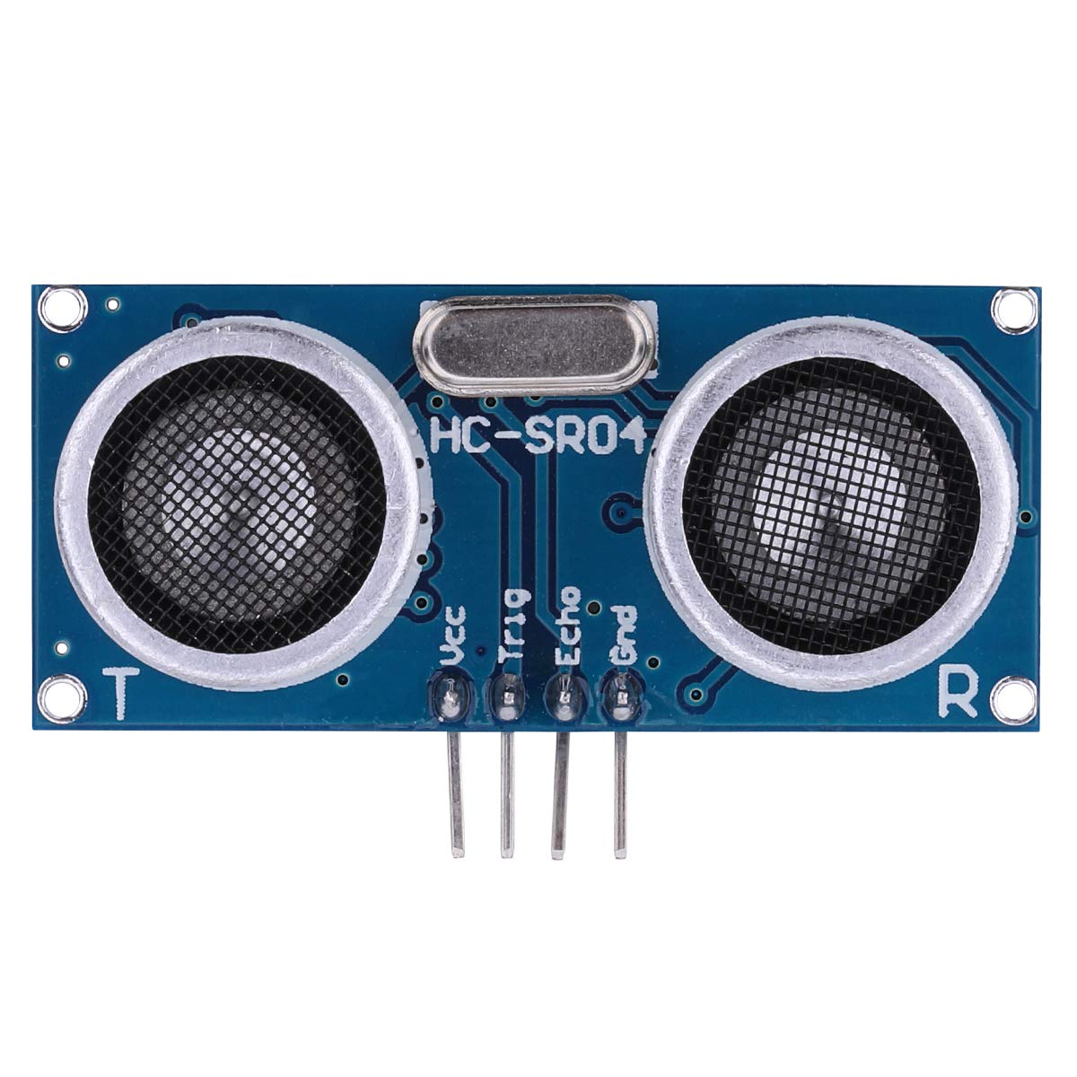
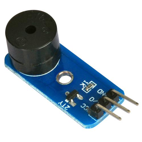
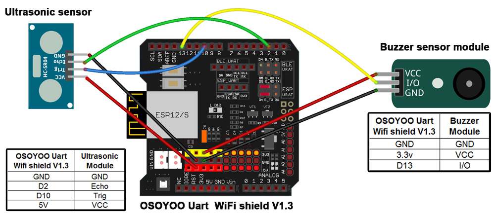
Step 4: Connect ultrasonic module, buzzer module with OSOYOO Uart WiFi shield V1.3 as below connection diagram (If you complete wires in lesson 5, please skip this step)
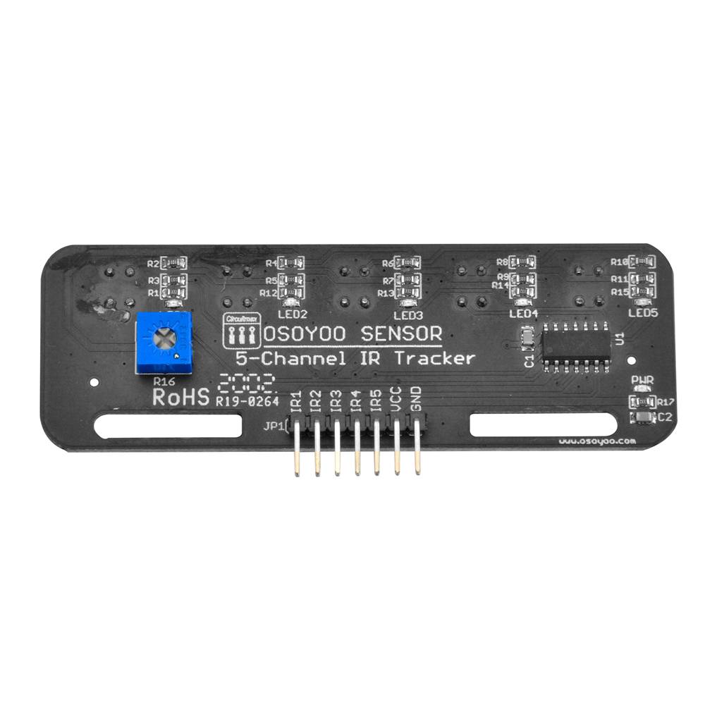
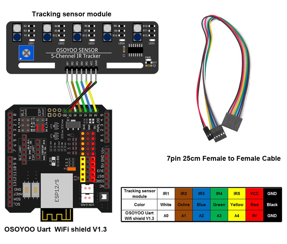
Step 5: Connect tracking sensor module with OSOYOO Uart WiFi shield V1.3 as below connection diagram (If you complete wires in lesson 4, please skip this step)
Note:
1)Please remember to adjust the sensitivity of tracking sensor modules as per link lesson 4 2)Please remember to do Ultrasonic sensor direction alignment as per link lesson 5
✅ This tutorial was written for the OSOYOO V2.1 Robot Car Kit
All 8 lessons, sample code, and circuit diagrams on this page are designed specifically for this kit.
Buy direct from OSOYOO Store and save 10% — plus get free shipping on orders over $70.
OSOYOO V2.1 Robot Car Kit
🔋 With battery & charger: $61.02 $67.80
— code ROBOTCAR10
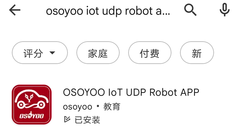
search “Osoyoo IoT UDP Robot APP” in
Google Play or Apple Store(If you can not find this APP in Google Play,
you can directly download the APP from following link: https://osoyoo.com/driver/udp-app.apk)
Step 1) Download OSOYOO Wi-Fi UDP Robot Car control APP
In Google Play or Apple Store, please search keywords “OSOYOO IoT UDP Robot APP”, you will find a red icon APP as following (Note: If you can not find this APP in Google Play, you can directly download the APP from following link: https://osoyoo.com/driver/udp-app.apk ):
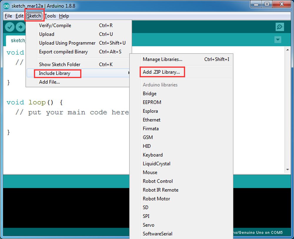
Step 2) Please download the library zip file from WiFiEsp-master .Open IDE ->click Sketch ->Include Library ->Add .ZIP library , then load above zip file into sketch.
Step 3) Sketch code Installation:
Osoyoo V2 Robot Car can work in two WIFI modes: STA mode and AP mode. The sketches for these two modes are different. Let’s explain these two modes one by one
A)STA mode In STA mode, V2.1 Robot Car will be a client device of your LAN router. You need save the SSID name and password of your LAN router in sketch.
Once the sketch is running, your router DHCP service will assign an IP address to your robot car and your APP will use this IP address to access your car.
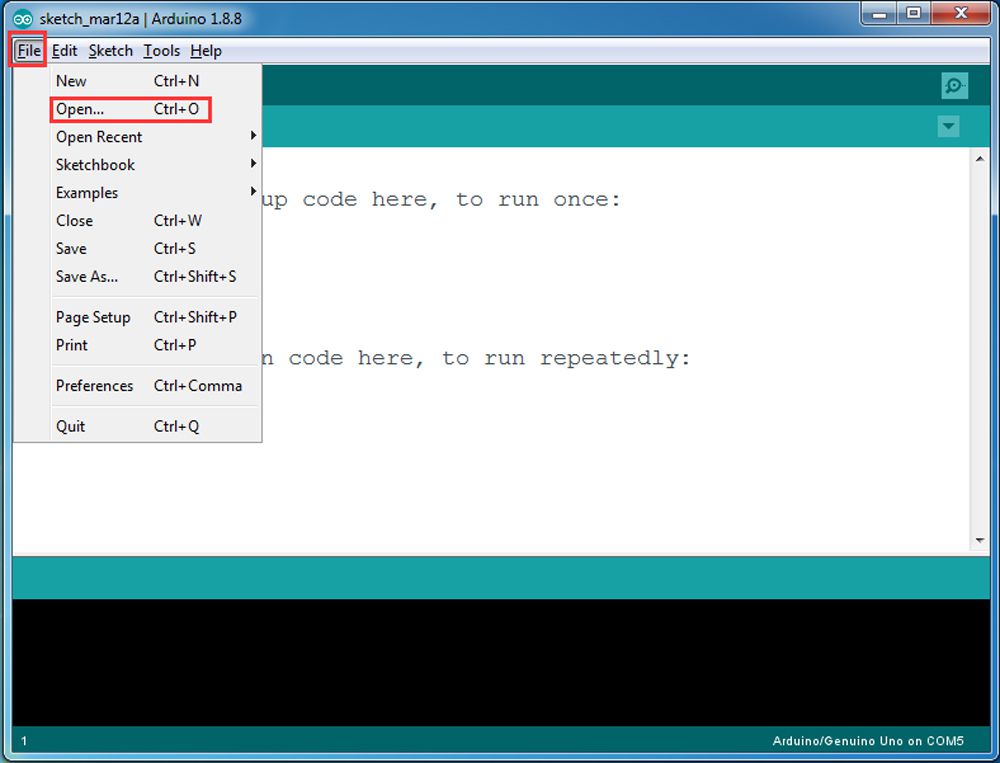
1) Please download STA mode sketch code from v2smartcar-lesson6A . Unzip the file, you will see a folder “v2smartcar-lesson6A”. Open IDE -> click file -> click Open -> choose code “v2smartcar-lesson6A.ino” in v2smartcar-lesson6A folder, load the code into your board
2) You need change the code Line 96 and Line 98 :
char ssid[] = “YOUR_ROUTER_SSID”; // replace this with your router wifi SSID
char pass[] = “YOUR_ROUTER_WIFI_PASSWORD”; // replace with your wifi password
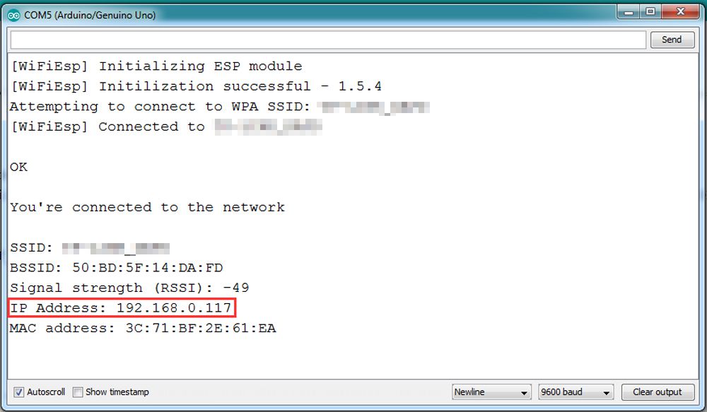
3) Upload the sketch to your board. Finally, click the Serial monitor window in upper right corner of IDE, you will see following result:
In above picture, the 192.168.0.117 is your robot car IP address. We will set this IP address to your APP so that APP can exchange data with the robot car.
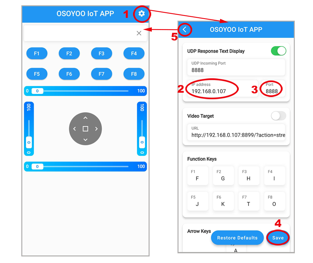
4) Connect your phone with the same router Wi-Fi SSID as the Arduino board. Open the APP, click “settings icon(1)” to enter setting UI, enter your robot car IP address and Port to 8888, click Save, then click back icon(5) to back control UI.
Example: If your Robot Car IP is 192.168.0.107, you can set the APP as following pictures:
Now your Robot car is connected to your LAN, you can use Mobile phone under same LAN to control the robot car. If your APP is in WAN, you need to go to your Router Control Panel and use Router IP to control the car. This feature makes our robot car A REAL INTERNET OF THING device
B)AP mode
Sometimes we do not have a LAN or WIFI Router. In order to control the car, we need to use AP mode.
When working in AP mode, our robot car itself will become a WIFI Hot Spot. Our cell phone can connect to Robot Car as its wifi client. The IP address of Robot is fixed as 192.168.4.1 and It is not connected to WAN.
1) Please download sketch from following link: v2smartcar-lesson6B. Unzip the file, you will see a folder “v2smartcar-lesson6B”. Open IDE -> click file -> click Open -> choose code “v2smartcar-lesson6B.ino” in v2smartcar-lesson6B folder, load the code into your board
2) Open Serial monitor, and you will see a similar result as STA mode. A new WIFI SSID “osoyoo_robot” with IP address 192.168.4.1 will show up in the window. This means your Robot car has a WIFI Hot Spot name “osoyoo_robot” , its IP address is 192.168.4.1
3) Connect your cell phone to “osoyoo_robot” wifi hot_spot, and set IP address as “192.168.4.1” and port to 8888 to your APP Setting section
Now your Robot car become a WIFI Hot Spot, you can use Mobile phone control the robot car.
Final Testing:
Trun on the car. Now click Setting to set up robot IP address.
A) In STA mode, you need connect cell phone to the same LAN ssid of your robot car and set IP address same as the Robot IP showed in Serial Monitor.
B) In AP mode , you need contact your cell phone to “osoyoo_robot” wifi hot_spot and set IP address as 192.168.4.1
you can click the ◄ ► ▲ ▼ direction keys to make the car move. Use || pause key to stop the car movement.
If you click F8 key, the car will do obstacle avoidance auto driving similar to Lesson 5
If you click F7 key, the car will do link tracking auto driving similar to lesson 4
Note: F1~F6 are further development functions in the future.
FAQ:
Q1)How to tune the robot car speed? A: If you want change the speed performance of the robot car, please following parameters in line 11 to 13:
SPEED value determines forward moving speed
TURN_SPEED value determines turning speed
SHIFT_SPEED value determines parallel shifting speed
Q 2)What happened when you press buttons in OSOYOO WiFi UDP Robot Car APP ? A: When you press a button of the APP, APP will send a single-letter message through UDP protocol to target device (in this example, our WIFI Shield)
Button
UDP message
F1
F
F2
G
F3
H
F4
I
F5
J
F6
K
▲
A
▼
B
►
R
◄
L
square
E
F7
O
F8
T
Q3)How does the board handle the UDP command?
Following switch(c) statements in v2smartcar-lesson6 sketch file are handling the UDP command
            switch (c)    //serial control instructions
            {

               case 'A':Drive_Status=MANUAL_DRIVE; Drive_Num=GO_ADVANCE;  WorkMode="GO_ADVANCE";break;
               case 'L':Drive_Status=MANUAL_DRIVE; Drive_Num=GO_LEFT; WorkMode="GO_LEFT";break;
               case 'R':Drive_Status=MANUAL_DRIVE; Drive_Num=GO_RIGHT;WorkMode="GO_RIGHT";break;
               case 'B':Drive_Status=MANUAL_DRIVE; Drive_Num=GO_BACK;WorkMode="GO_BACK";break;
               case 'E':Drive_Status=MANUAL_DRIVE; Drive_Num=STOP_STOP;WorkMode="STOP_STOP";break;
               case 'O':Drive_Status=AUTO_DRIVE_UO;Serial.println("go OBSTACLE");WorkMode="OBSTACLE";break;
               case 'T':Drive_Status=AUTO_DRIVE_LF;WorkMode="line follow";break;
               case 'G':track_speed=track_speed+10;
                        if(track_speed>200) track_speed=200
                         ;break;
               case 'J':track_speed=track_speed-10;
                        if(track_speed<80) track_speed=80
                         ;break;
               default:break;
              } //END OF ACTION SWITCH
In above code, c in switch() brackets is the UDP data sent from cell phone APP. Once APP ▲ key is pressed, then case ‘A’ … line will handle the command and make car move ahead.
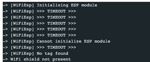
Q4) The serial window show error ” [WiFiEsp] >>> TIMEOUT>>>”
Please check the jumper caps and make sure that Jumper caps connect E_TX pin to D4 and E_RX pin to D5 as the Step 2 in hardware installation
🤖 Start building your V2.1 Robot Car today
Official kit for this tutorial · WiFi + Bluetooth + 8 project lessons included
Use exclusive reader code ROBOTCAR10 for 10% off — buy direct and save vs Amazon
I am trying to use the first version of the WIFI code (STA Mode). I got the code to compile and load into the robot, however, I am getting an error stating -Cannot initialize ESP module, WIFI Shield is not present.
1. Please confirm that connect E_TX (Esp8266 TX) pin to Arduino D4(UNO soft serial RX) and E_RX(ESP8266_RX) pin to D5(UNO software serial TX) as the step 2 in the installation
2. Please check that you change the ssid and psw to your own before uploading the code.
3. Please confirm that the voltage is more than 7.2V.
Still waiting on answer to my question for Lesson 5. So now I have moved on to Lesson 6A. All connections made and sketch installed in board. I have entered my router ssid and password into sketch. I have chosen STA mode. When I open the serial monitor I get the following message. “W[WIFIESP} Initializing ESP Module”
“WiFi ESP TIMEOUT” “cannot initialize ESP module” “WiFi Shield not present” . I have checked the router but it does not show the Shield as a connected device. Can you help? I have both 5G and 2.4G available.
Regards, Jim Robb
I have moved on to Lesson 6A. All connections made and sketch installed in board. I have entered my router ssid and password into sketch. I have chosen STA mode. When I open the serial monitor I get the following message. “W[WIFIESP} Initializing ESP Module, W[WiFiESP] Initilization successful, W[WiFiESP] Attempting to connect to [ssid] , w[WiFiESP] failed connecting to [ssid]. etc ——-
The router does not show the Shield as a connected device. Can you help? I have both 5G and 2.4G available.
Regards, Jim Robb
based on your description, you are very very very very likely to have written wrong SSID or PASSWORD in the sketch code. Please double check every letter of your SSID and password in the code include space and everything. Also make sure your robot car is connecting to a wifi router, not to a cell phone hotspot. Cell phone hotspot might block ESP8266 as STA client.
Hi,
You were correct I had missed out one of the letters in the password. The print is so small my old eyes are not so good for that.
Many thanks for your help.
Regards, Jim.
when I try to sketch lesson 6 I get the following error message
C:\Users\Steve\Desktop\v2smartcar-lesson6A\v2smartcar-lesson6A.ino:11:10: fatal error: WiFiEspUdp.h: No such file or directory
#include
^~~~~~~~~~~~~~
compilation terminated.
exit status 1
Compilation error: WiFiEspUdp.h: No such file or directory
Did I miss something?
I redownloaded the first set and sketched it now I’m getting
[WiFiEsp] >>> TIMEOUT >>>
[WiFiEsp] >>> TIMEOUT >>>
[WiFiEsp] >>> TIMEOUT >>>
[WiFiEsp] >>> TIMEOUT >>>
[WiFiEsp] Cannot initialize ESP module
[WiFiEsp] >>> TIMEOUT >>>
[WiFiEsp] No tag found
WiFi shield not present
1. Please confirm that connect E_TX (Esp8266 TX) pin to Arduino D4(UNO soft serial RX) and E_RX(ESP8266_RX) pin to D5(UNO software serial TX) as the step 2 in the installation
2. Please check that you change the ssid and psw to your own before uploading the code.
You need change the code Line 96 and Line 98 :
char ssid[] = “YOUR_ROUTER_SSID”; // replace this with your router wifi SSID
char pass[] = “YOUR_ROUTER_WIFI_PASSWORD”; // replace with your wifi password
3. Please confirm that the voltage is more than 7.2V.
I have uploaded this sketch ok. However how can I see the debug output in the Serial Monitor ?
When connected via a USB cable the serial monitor shows output. However, as soon as the car is untethered the connection is lost.
When connected the monitor say to open a browser window, which is where I assume I will see the monitor, however, the browser does not find a page at the location stated.
9:48:21.699 -> [WiFiEsp] Initializing ESP module
09:48:26.458 -> [WiFiEsp] Initilization successful – 1.5.4
09:48:26.525 -> Attempting to connect to WPA SSID: BT-XXXXXX
09:48:31.543 -> [WiFiEsp] Connected to BT-XXXXX
09:48:31.607 -> You’re connected to the network
09:48:31.642 ->
09:48:31.642 -> IP Address: 192.168.1.220
09:48:31.677 ->
09:48:31.677 -> To see this page in action, connect to BT-6MA89Q and open a browser to http://192.168.1.220
09:48:31.772 ->
09:48:31.772 -> Listening on port 8888
I’m running into the same problem that many others seem to have hit. I can’t get the wifi module to connect at all. I’ve swapped two different UNOs, two different Mega2560s, and all the wiring I can. I have the Arduino powered from a 12V wall wart (I had everything on the robot, but pulled it apart to make sure that wasn’t the issue).
The code stops running after the WiFi.init call returns with a WL_NO_SHIELD value, so this isn’t an issue with the network settings. I’ve even tried the network scanner example from the wifi library to see if that might be an issue.
On the UNO I leave the jumpers in place across D4/E_TX and D5/E_RX. On the 2560 I’ve various pairings of E_RX/D1[89] and E_TX/D1[89]. I’m stuck here. Do I have a bad board or is there more testing I can do?
Ok, got thru the first part. The shield starts out at 115200bps and without that there’s no communication. Now I can get the shield connected to my local wifi. But, the part that says connect a browser to http://addr:8888 doesn’t work. Shouldn’t the shield be using TCP here? I can see the device on my local network.
11:30:34:179 -> [WiFiEsp] Connected to xxxxx
11:30:34:215 -> You’re connected to the network
11:30:34:251 ->
11:30:34:251 -> IP Address: 192.168.54.36
11:30:34:280 -> 3C:E9:0E:E5:4D:44
11:30:34:301 ->
11:30:34:301 -> To see this page in action, connect to xxxxx and open a browser to http://192.168.54.36:8888
11:30:34:407 -> Listening on port 8888


I am trying to use the first version of the WIFI code (STA Mode). I got the code to compile and load into the robot, however, I am getting an error stating -Cannot initialize ESP module, WIFI Shield is not present.
1. Please confirm that connect E_TX (Esp8266 TX) pin to Arduino D4(UNO soft serial RX) and E_RX(ESP8266_RX) pin to D5(UNO software serial TX) as the step 2 in the installation
2. Please check that you change the ssid and psw to your own before uploading the code.
3. Please confirm that the voltage is more than 7.2V.
Still waiting on answer to my question for Lesson 5. So now I have moved on to Lesson 6A. All connections made and sketch installed in board. I have entered my router ssid and password into sketch. I have chosen STA mode. When I open the serial monitor I get the following message. “W[WIFIESP} Initializing ESP Module”
“WiFi ESP TIMEOUT” “cannot initialize ESP module” “WiFi Shield not present” . I have checked the router but it does not show the Shield as a connected device. Can you help? I have both 5G and 2.4G available.
Regards, Jim Robb
I have moved on to Lesson 6A. All connections made and sketch installed in board. I have entered my router ssid and password into sketch. I have chosen STA mode. When I open the serial monitor I get the following message. “W[WIFIESP} Initializing ESP Module, W[WiFiESP] Initilization successful, W[WiFiESP] Attempting to connect to [ssid] , w[WiFiESP] failed connecting to [ssid]. etc ——-
The router does not show the Shield as a connected device. Can you help? I have both 5G and 2.4G available.
Regards, Jim Robb
I refer to my question of December 13th at 9.16pm. Have you any suggestions why my Shield will not connect to my WiFi ESP?
Regards, Jim Robb
hi, James Robb,
based on your description, you are very very very very likely to have written wrong SSID or PASSWORD in the sketch code. Please double check every letter of your SSID and password in the code include space and everything. Also make sure your robot car is connecting to a wifi router, not to a cell phone hotspot. Cell phone hotspot might block ESP8266 as STA client.
Hi,
You were correct I had missed out one of the letters in the password. The print is so small my old eyes are not so good for that.
Many thanks for your help.
Regards, Jim.
when I try to sketch lesson 6 I get the following error message
C:\Users\Steve\Desktop\v2smartcar-lesson6A\v2smartcar-lesson6A.ino:11:10: fatal error: WiFiEspUdp.h: No such file or directory
#include
^~~~~~~~~~~~~~
compilation terminated.
exit status 1
Compilation error: WiFiEspUdp.h: No such file or directory
Did I miss something?
I redownloaded the first set and sketched it now I’m getting
[WiFiEsp] >>> TIMEOUT >>>
[WiFiEsp] >>> TIMEOUT >>>
[WiFiEsp] >>> TIMEOUT >>>
[WiFiEsp] >>> TIMEOUT >>>
[WiFiEsp] Cannot initialize ESP module
[WiFiEsp] >>> TIMEOUT >>>
[WiFiEsp] No tag found
WiFi shield not present
1. Please confirm that connect E_TX (Esp8266 TX) pin to Arduino D4(UNO soft serial RX) and E_RX(ESP8266_RX) pin to D5(UNO software serial TX) as the step 2 in the installation
2. Please check that you change the ssid and psw to your own before uploading the code.
You need change the code Line 96 and Line 98 :
char ssid[] = “YOUR_ROUTER_SSID”; // replace this with your router wifi SSID
char pass[] = “YOUR_ROUTER_WIFI_PASSWORD”; // replace with your wifi password
3. Please confirm that the voltage is more than 7.2V.
I have uploaded this sketch ok. However how can I see the debug output in the Serial Monitor ?
When connected via a USB cable the serial monitor shows output. However, as soon as the car is untethered the connection is lost.
When connected the monitor say to open a browser window, which is where I assume I will see the monitor, however, the browser does not find a page at the location stated.
9:48:21.699 -> [WiFiEsp] Initializing ESP module
09:48:26.458 -> [WiFiEsp] Initilization successful – 1.5.4
09:48:26.525 -> Attempting to connect to WPA SSID: BT-XXXXXX
09:48:31.543 -> [WiFiEsp] Connected to BT-XXXXX
09:48:31.607 -> You’re connected to the network
09:48:31.642 ->
09:48:31.642 -> IP Address: 192.168.1.220
09:48:31.677 ->
09:48:31.677 -> To see this page in action, connect to BT-6MA89Q and open a browser to http://192.168.1.220
09:48:31.772 ->
09:48:31.772 -> Listening on port 8888
This web address just doesn’t load http://192.168.1.220 – Any Ideas ?
I’m running into the same problem that many others seem to have hit. I can’t get the wifi module to connect at all. I’ve swapped two different UNOs, two different Mega2560s, and all the wiring I can. I have the Arduino powered from a 12V wall wart (I had everything on the robot, but pulled it apart to make sure that wasn’t the issue).
The code stops running after the WiFi.init call returns with a WL_NO_SHIELD value, so this isn’t an issue with the network settings. I’ve even tried the network scanner example from the wifi library to see if that might be an issue.
On the UNO I leave the jumpers in place across D4/E_TX and D5/E_RX. On the 2560 I’ve various pairings of E_RX/D1[89] and E_TX/D1[89]. I’m stuck here. Do I have a bad board or is there more testing I can do?
[WiFiEsp] Initializing ESP module
[WiFiEsp] >>> TIMEOUT >>>
[WiFiEsp] >>> TIMEOUT >>>
[WiFiEsp] >>> TIMEOUT >>>
[WiFiEsp] >>> TIMEOUT >>>
[WiFiEsp] >>> TIMEOUT >>>
[WiFiEsp] Cannot initialize ESP module
[WiFiEsp] >>> TIMEOUT >>>
[WiFiEsp] No tag found
WiFi shield not present
Ok, got thru the first part. The shield starts out at 115200bps and without that there’s no communication. Now I can get the shield connected to my local wifi. But, the part that says connect a browser to http://addr:8888 doesn’t work. Shouldn’t the shield be using TCP here? I can see the device on my local network.
11:30:34:179 -> [WiFiEsp] Connected to xxxxx
11:30:34:215 -> You’re connected to the network
11:30:34:251 ->
11:30:34:251 -> IP Address: 192.168.54.36
11:30:34:280 -> 3C:E9:0E:E5:4D:44
11:30:34:301 ->
11:30:34:301 -> To see this page in action, connect to xxxxx and open a browser to http://192.168.54.36:8888
11:30:34:407 -> Listening on port 8888
Do you have a model for App inventor as a guide
what kind of model do you need?please email to [email protected]
Eu gostaria de replicar a app, mas estou com dificuldades. Criaram a app com o MIT Inventor; se sim, como?
Sorry, we don’t know the reason why you want to copy this APP?