The OSOYOO Magic I/O Shield for Arduino is a powerful board for the beginners. With this Magic board, we can easily connect various sensors and actuators much easier than before.
In this lesson, we will show how to gradually change the luminance of an LED Module through programming. Since the pulsing light looks like breathing, we give it a magical name – breathing LED. We’ll accomplish this effect with pulse width modulation (PWM).
OSOYOO Basic Board for Arduino (Fully compatible with Arduino UNO rev.3) x 1
OSOYOO Magic I/O Shield for Arduino x1
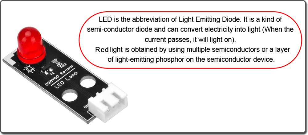
Red LED Module x 1
OSOYOO 3-Pin PnP cable x 1
USB Cable x 1
PC x 1
What is PWM?
Pulse Width Modulation, or PWM, is a technique for getting analog results with digital means. In simple, PWM pin can generate “analog-like” current output controlled by computer program. Following words are detailed introduction about PWM, if you are not interested in such tech detail, you can skip them and directly go to HOW TO MAKE section.
Digital control is used to create a square wave, a signal switched between on and off. This on-off pattern can simulate voltages in between full on (5 Volts) and off (0 Volts) by changing the portion of the time the signal spends on versus the time that the signal spends off. The duration of “on time” is called the pulse width. To get varying analog values, you change, or modulate, that pulse width.
To get varying analog values, you change, or modulate, that pulse width. If you repeat this on-off pattern fast enough with an LED for example, the result is as if the signal is a steady voltage between 0 and 5V controlling the brightness of the LED. (See the PWM description on the official website of Arduino).
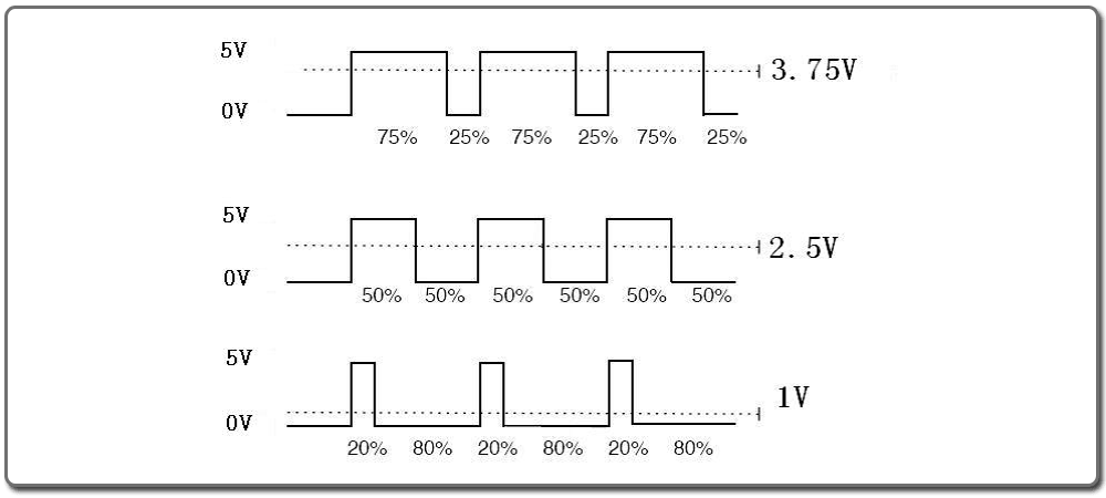
We can see from the top oscillogram that the amplitude of the DC voltage output is 5V. However, the actual voltage output is only 3.75V through PWM because the high level only takes up 75% of the total voltage within a period.
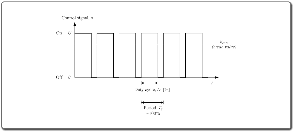
Here is an introduction to the three basic parameters of PWM:
Duty cycle describes the proportion of “on” time to the regular interval or period of time.
Period describes the reciprocal of pulses in one second.
The voltage amplitude here is 0V–5V.
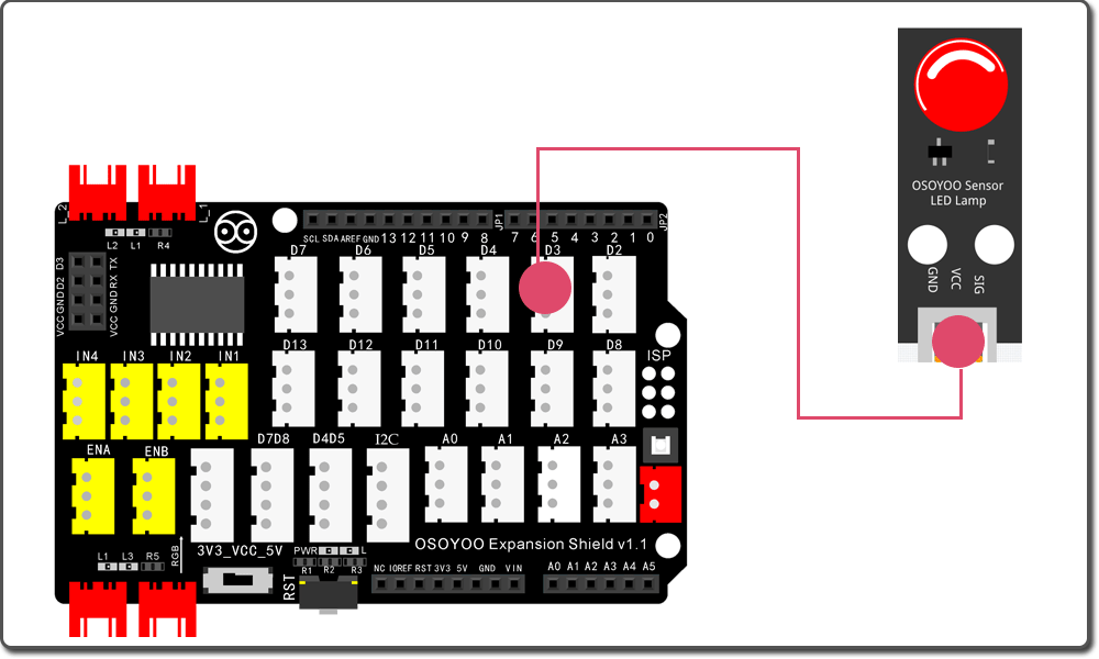
There are 6 pins on most compatible Arduino boards marked with ‘PWM’ next to the pin number (on some boards it is an “~” symbol) – these pins are PWM pins.We use the pin D3 to control the LED module here.
First, please plug Osoyoo Magic I/O shield into UNO board:
Then connect the LED module to the D3 port of the Magic I/O shield with a 3-pin PNP cable as below:
Notice:
You cannot directly connect a LED to a battery or voltage source. Firstly, because the LED has a positive and a negative lead and will not light if they are the wrong way around; Secondly, a LED must be used with a resistor to limit or ‘choke’ the amount of current flowing through the LED – otherwise the LED may be burn out!
Notice: Shut off your battery or Unplug your power adapter when upload sketch code to OSOYOO Basic Board for Arduino.
After above operations are completed, connect the OSOYOO Basic Board for Arduino to your computer using the USB cable. The green power LED (labelled PWR) should go on.
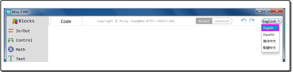
Open the Graphical Programming softwareMixly, if Mixly is not English, you should change the language first:
You can download the code directly, then click “Open” in Mixly to choose the code you download:
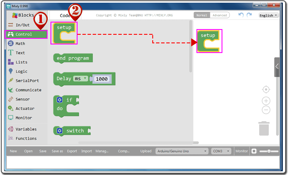
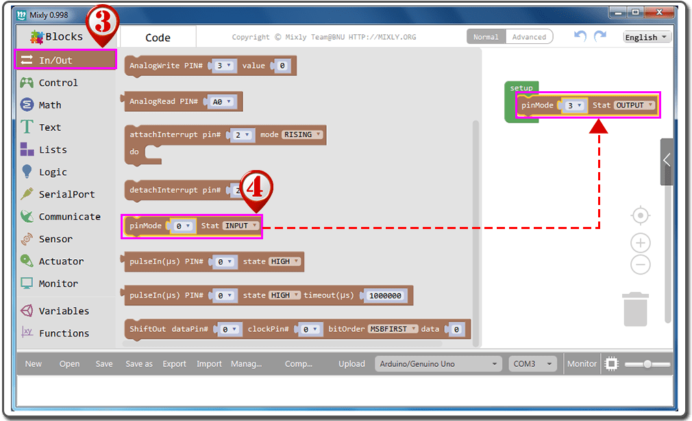
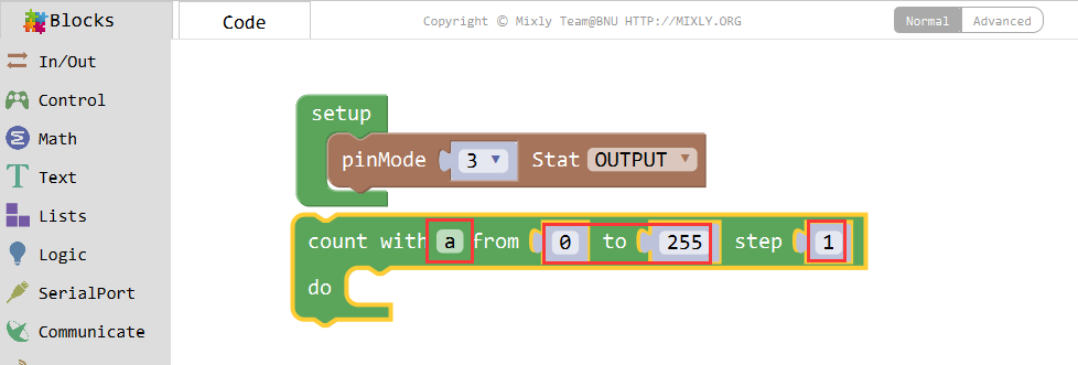
Drag the “pinMode” under “Setup” block, fit the two blocks, and define the parameter to “pinMode 3 Stat OUTPUT“;
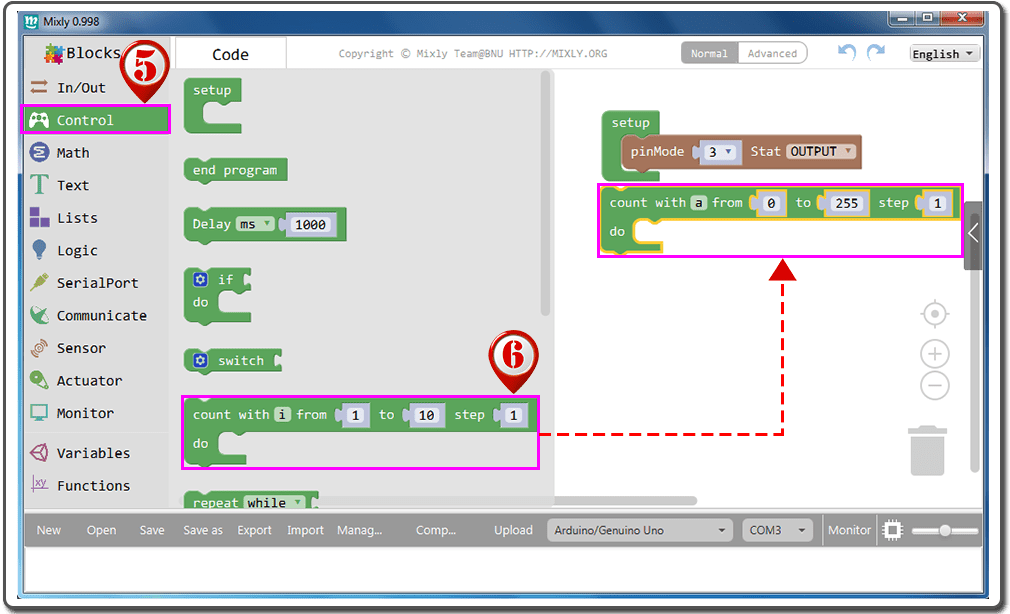
Click “Control” block;
Drag the “count with” block to the blank space, and edit the parameter to“count with a from 0 to 255 step 1” .
This loop should ascend from a=0, in each loop cycle, variable “a” keeps adding 1 until a=255 , then the loop will finish.
When 0≤a≤255, assign its value to pin 3 of LED time after time, to let the LED get brighter. The LED will keep the present brightness for 10ms in each cycle.
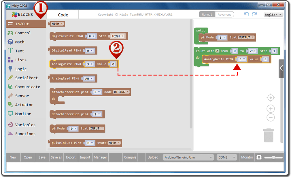
Click “In/Out” block;
Drag the “AnalogWrite PIN#” under “count with” block, fit the two blocks, and define the parameter to “AnalogWrite PIN# 3 value a“;
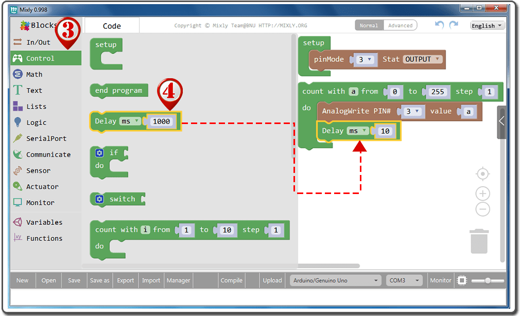
Click “Control” block;
Drag the “Delay” under “AnalogWrite PIN#” block, fit the two blocks, and define the parameter to “Delay ms 10“.
Set another for loop to let the LED get dimmer. The variable “a” value decreases from 255 to 0. We have assigned as value to Pin 3 in the first loop, thus we can just duplicate the combined block to get another. The LED will keep the present brightness for 10ms in each cycle.
Move the mouse over the “count with” block and right click to duplicate the blocks;
Drag the duplicated blocks to fit the above blocks;
Edit the parameter of the duplicated “count with” block to “count with a from 255 to 0 step –1″
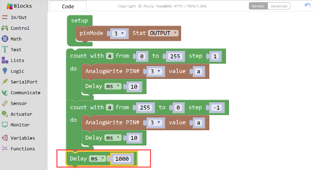
Set a delay of 1 second for the bulk of LED getting brighter and then dimmer. Then run this LED breathing repeatedly.
Click “Control” block;
Drag “Delay” block below “count with” block, fit the two blocks, and define the parameter to“Delay ms1000”.
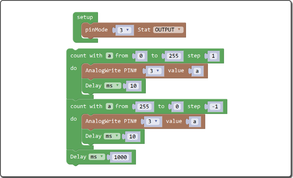
The whole program blocks are as following:
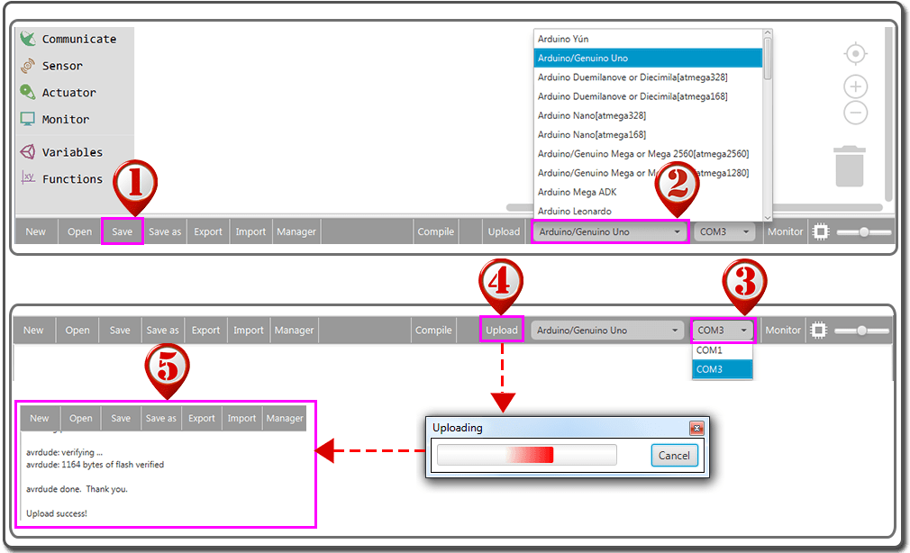
Click Save after programming is done.
Select the board type and serial port before uploading. For instause an UNO board, just select Arduino/Genuino Uno: if you use a Mega2560, select Arduino/Genuino Mega or Mega2560.
Select the serial device of the OSOYOO Basic Board for Arduino from the COM menu. This is likely to be COM3 or higher (COM1 and COM2 are usually reserved for hardware serial ports). To find out, you can disconnect your OSOYOO Basic Board for Arduino and re-open the menu; the entry that disappears should be the OSOYOO Basic Board for Arduino. Reconnect the board and select that serial port.
Next,upload the code. If the uploading fails, check and correct the code according to the prompts.
Finally, the status will change to ‘Upload success!’.
A few seconds after the upload finishes, you should see the LED gets brighter and brighter, and then slowly dimmer, just like breathing.


 Set another for loop to let the LED get dimmer. The variable “a” value decreases from 255 to 0. We have assigned as value to Pin 3 in the first loop, thus we can just duplicate the combined block to get another. The LED will keep the present brightness for 10ms in each cycle.
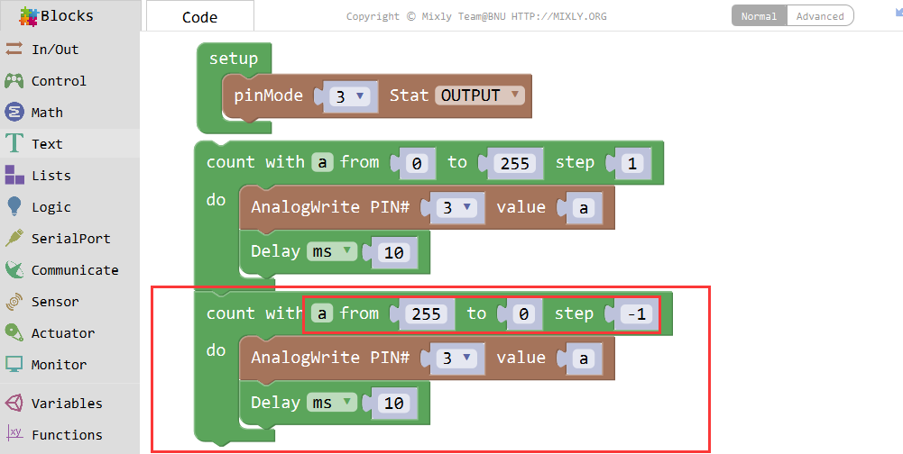

I believe “ms” should be changed to “milis”, 10 microsecond is to short for the ramping effect to be visible
Can you open the comment section on the following lesson?