| Name |
Image |
| 12864 LCD 3D Printer Kit |
 |
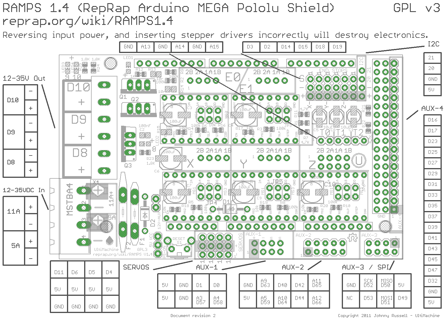
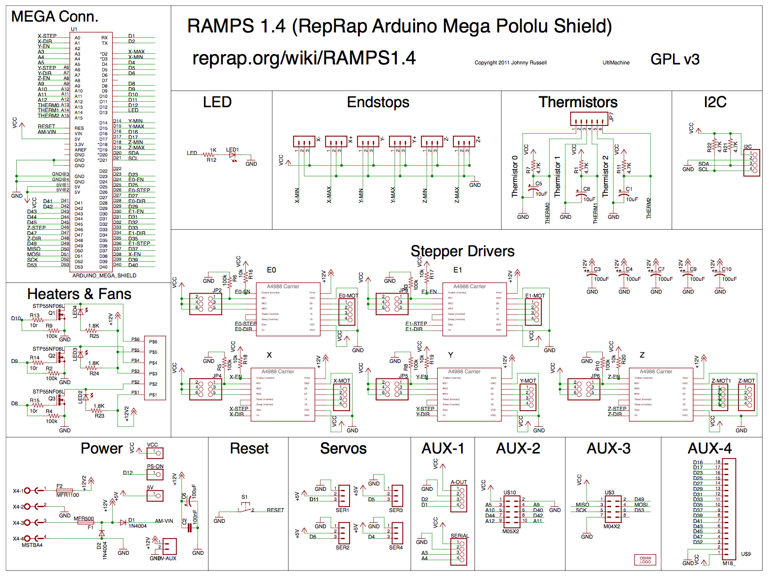
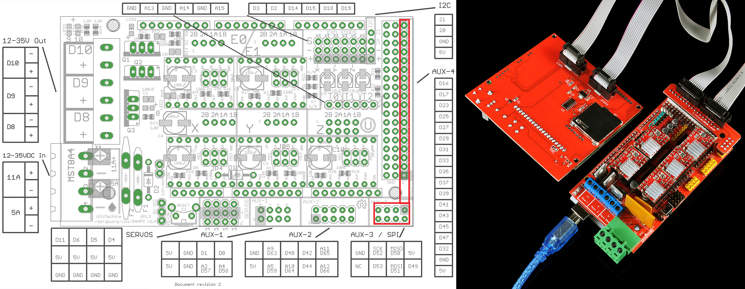
1. RAMPS 1.4 Schematic:
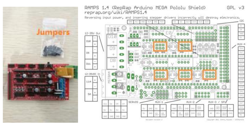
2. Insert Jumpers into RAMPS 1.4
The jumpers (included in the plastic bag) control the precision of the stepper motor movement. For the most precise stepping (1/16 micro-stepping), insert three jumpers into each of the areas outlined below:
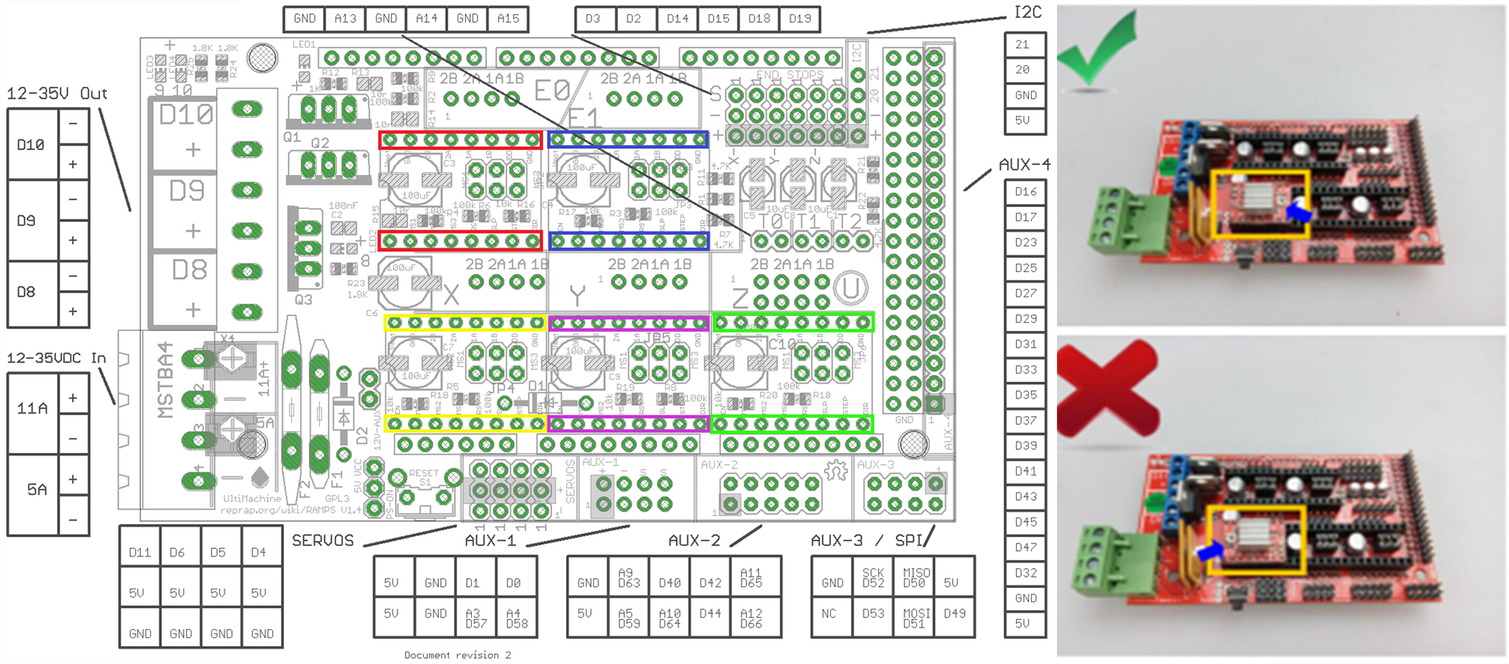
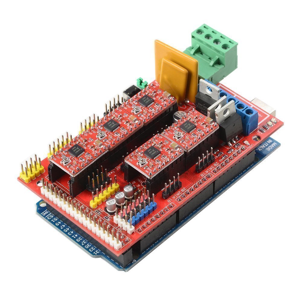
3. Install A4988 Drivers on RAMPS 1.4
MAKE SURE THE ORIENTATION IS CORRECT AS SHOWN BELOW! The potentiometer should face away from the “D10 D9 D8” side of the RAMPS 1.4 shield. We have seen many cases where stepper drivers were damaged due to incorrect orientation. Install the heat sinks on the stepper drivers, and make sure the heat sink does not touch multiple components on the driver — the clearance can be small, but it is there.
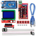
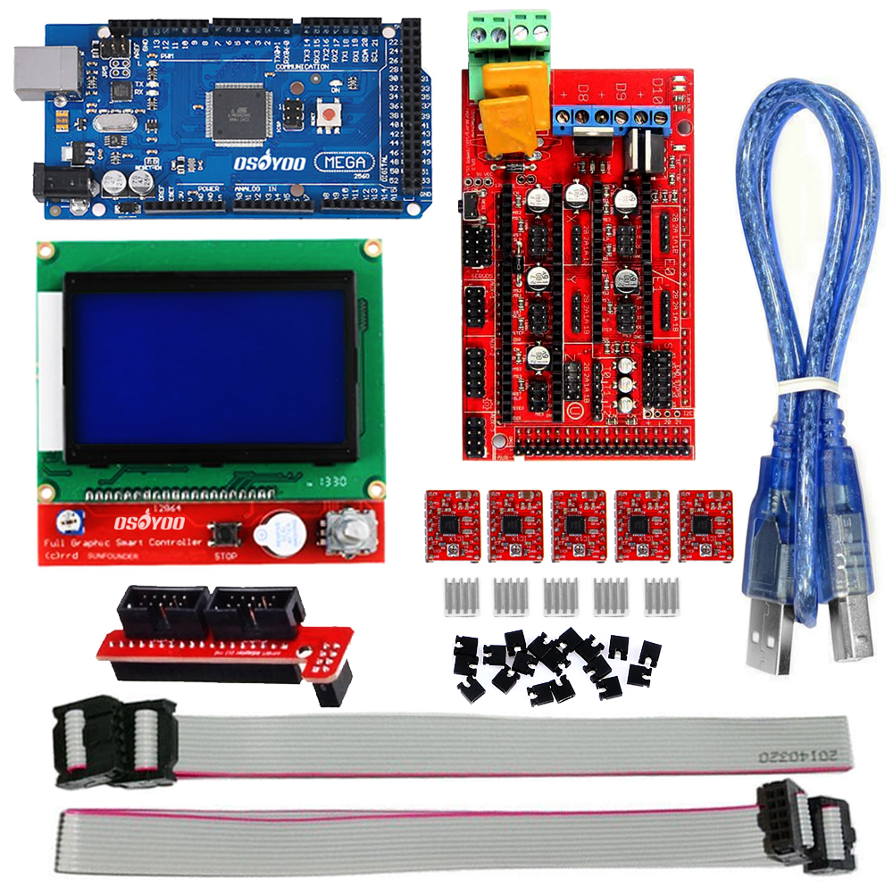
✅ Got the pinout? Now get the hardware.
If you’re wiring up a RepRap build, the OSOYOO RAMPS 1.4 Controller Kit
includes everything shown in this diagram — RAMPS 1.4 board, Mega2560,
5× A4988 stepper drivers, and a full graphic LCD 12864 smart display.
No hunting for parts separately.
4. Install the RAMPS 1.4 on the Mega 2560 Board
The Mega 2560 board’s USB port is directly under the RAMPS 1.4 shield’s “D8 D9 D10” area.
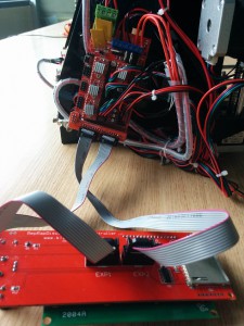
5. Install the 12864 LCD / 2004 LCD on RAMPS 1.4
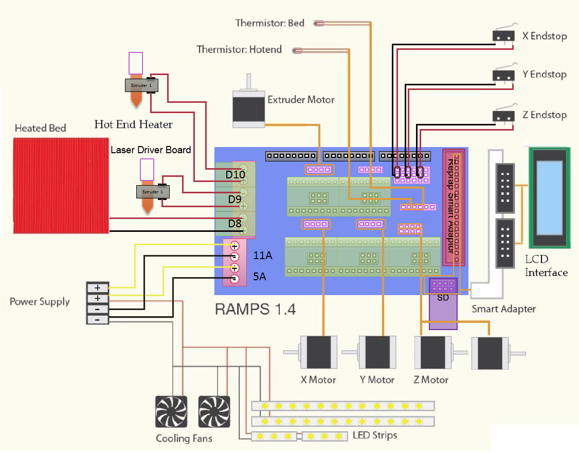
6. Connect Power, Motors, Thermistors, Hotend, Heatbed, and Fan
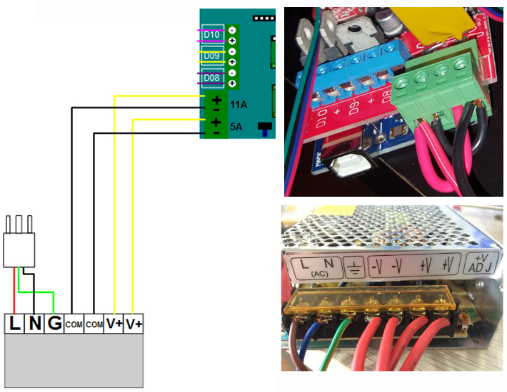
6.1. Connect Power
Connect your 12V power supply to the RAMPS shield. Reversing +/− or otherwise incorrectly connecting power can destroy your electronics and create a fire hazard. Get four spare wires and connect them to the two COM (V−) and the two V+ terminals. Connect the other ends to the RAMPS 1.4 shield’s power input: the first pin on the bottom is COM (−V), then V+, then COM, then V+ again, as shown below.
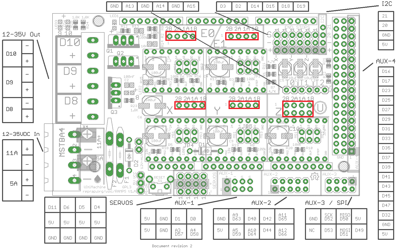
6.2. Connect Stepper Motors
The RAMPS board has connectors for the X, Y, Z, E0, and E1 stepper motors. The Z connector is doubled so you can plug two separate stepper motors into this single stepper driver. E0 and E1 are for your extruder stepper motors — if you have a single extruder, use E0.
ATTENTION: Do not use axis homing at this point!
When homing, the firmware moves each axis until it hits the endstop. If the stepper turns in the wrong direction, the printhead or bed will keep moving until it hits the mechanical end of the axis. You can only stop this by resetting the printer or turning off the power.
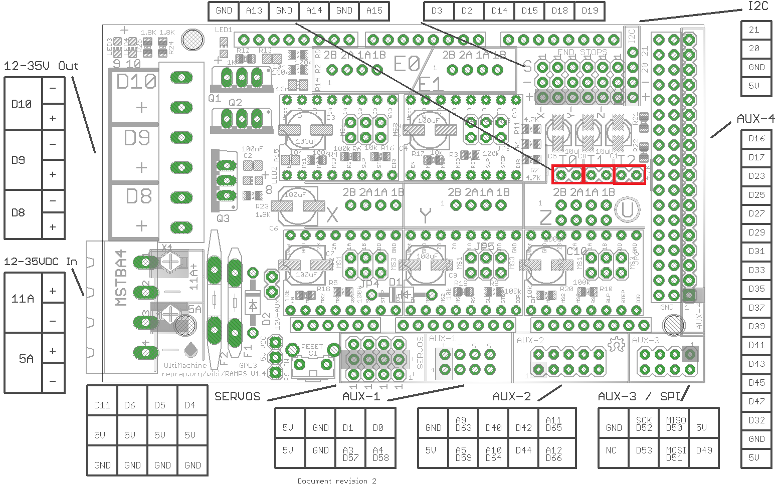
6.3. Connect Thermistors
From left to right: extruder 1 thermistor, heatbed thermistor, and extruder 2 thermistor. These are not polarity-sensitive. The thermistor leads must be electrically isolated from each other — small Teflon tubing works best for this.
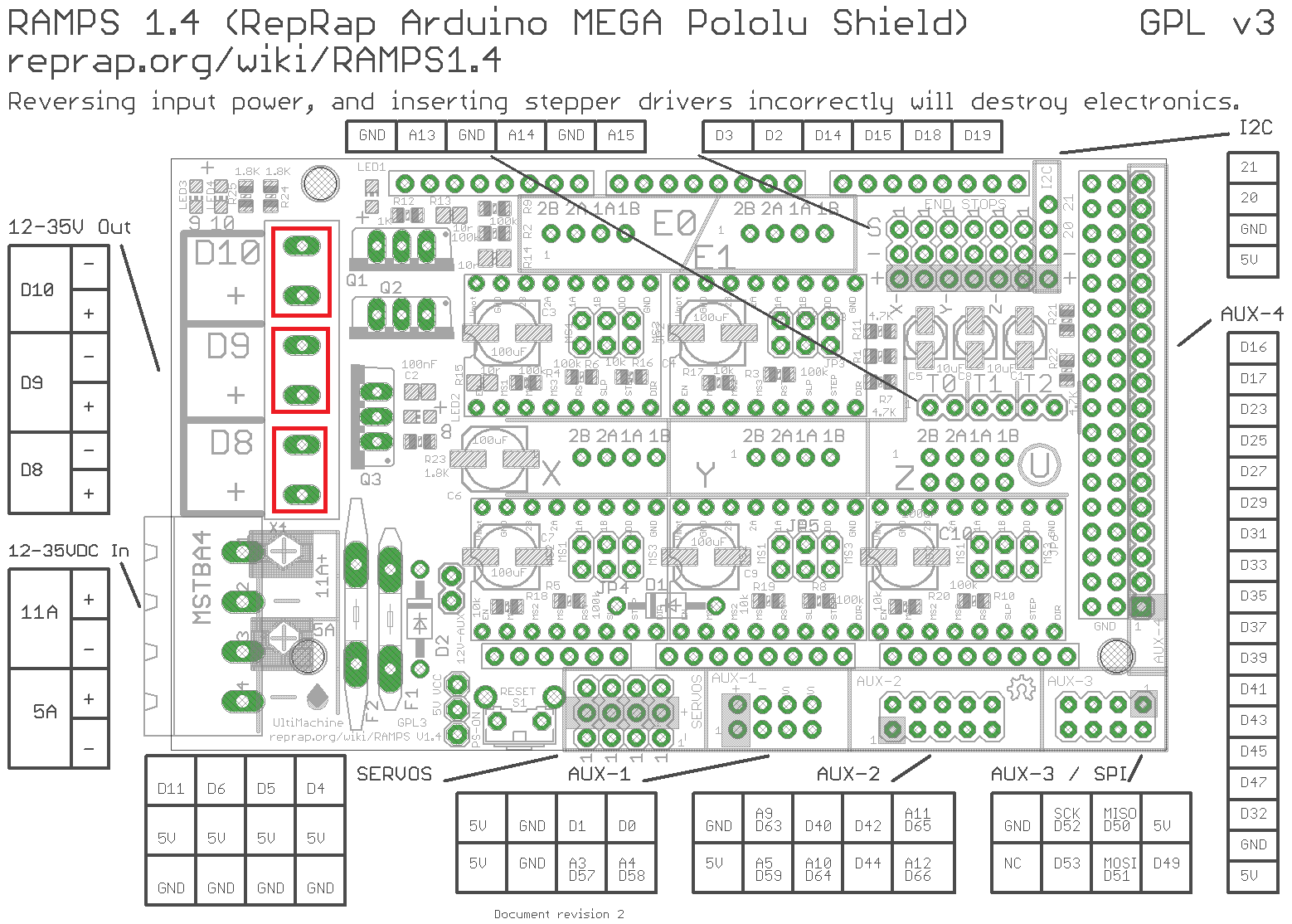
6.4. Connect Hotbed and Extruder
Plug the extruder 1 heater into D10, the heatbed heater into D8, and the fan (or a second extruder) into D9. Only the fan is polarity-sensitive.
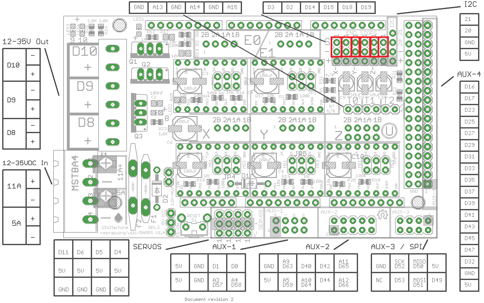
6.5. Endstop Connections
From left to right on the RAMPS 1.4, each column corresponds to xmin, xmax, ymin, ymax, zmin, and zmax.
Mechanical endstops are polarity-sensitive. Solder wires to the “COM” and “NC” leads, and connect them to the top two rows of the endstop area shown below — COM on the bottom row, NC on the top. If you are using an optical endstop, you will need all three pins.
In practice, most builders wire an endstop only to the minimum (zero point) for each axis and rely on software limits in the firmware to prevent the printer from going too far in the opposite direction.
7. Complete Assembly View
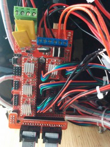
 .
.


were is pin D7 located im building a custom project and need it