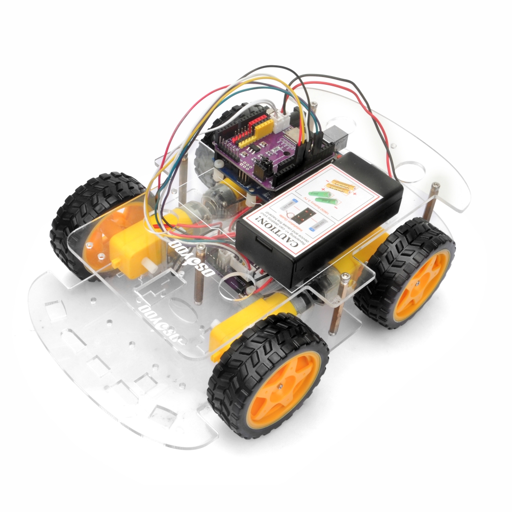
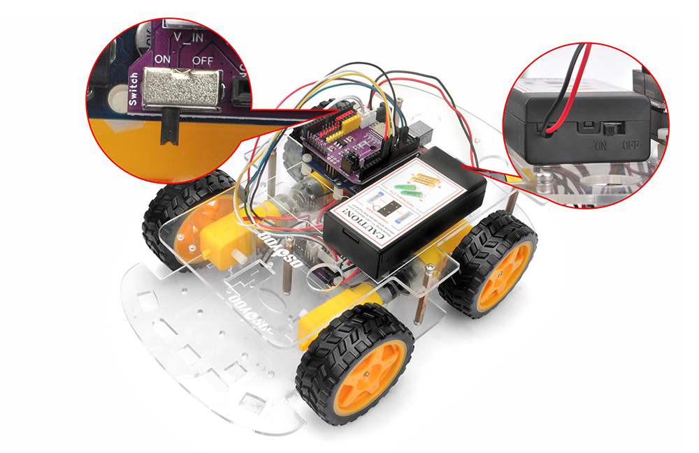
In this first lesson of the OSOYOO V3 Robot Car Kit, you will assemble the chassis and connect all the core components. The goal is to build a stable, working robot car platform ready for the lessons that follow. By the end of this lesson, the microcontroller, motor driver, power system, and chassis will all be in place and ready to test.
2Parts and Devices:
The following components are needed for this assembly. Please make sure you have all the parts before starting.
No.
Picture
Device
Qty.
Accessories
Link
1
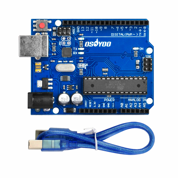
OSOYOO basic board
1
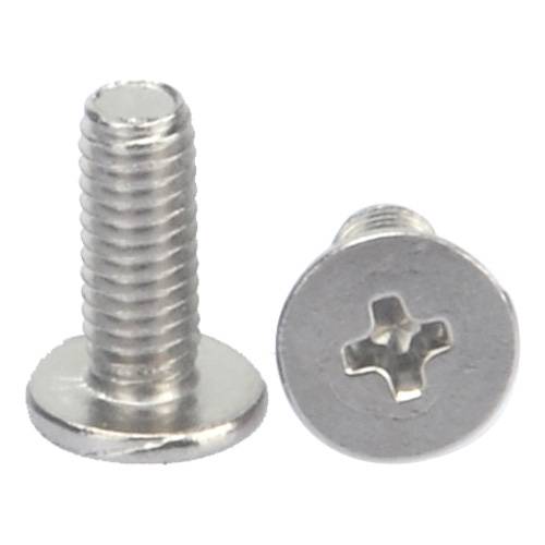
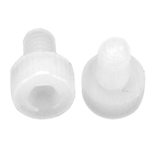
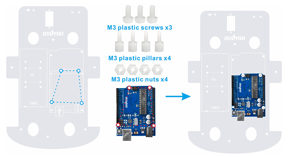
M3 Plastic Screw x 3
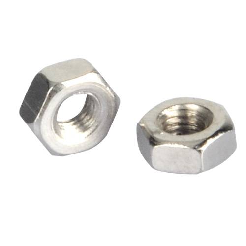
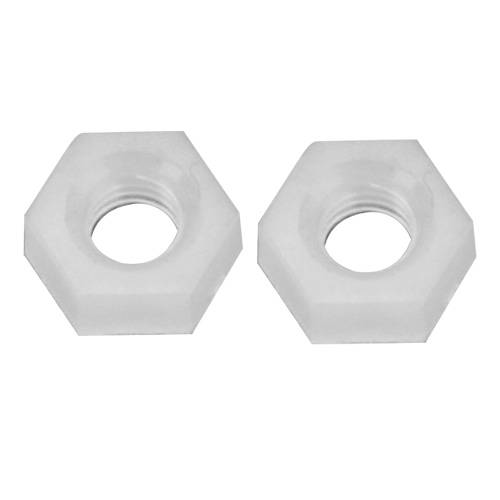
M3 Plastic Nut x 4
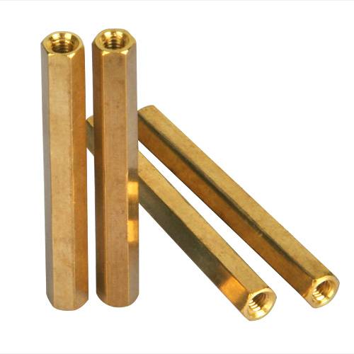
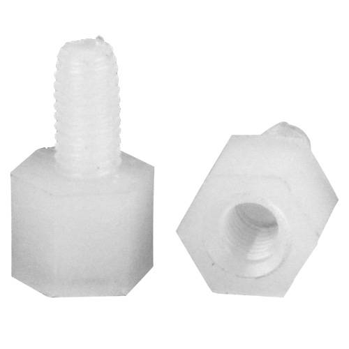
M3 Plastic Pillar x 4
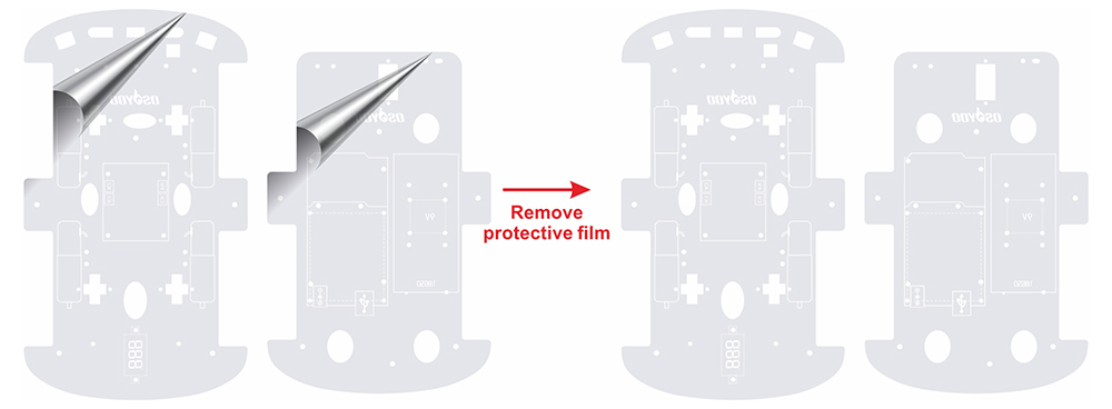
1) Remove the protective film from the upper and lower car chassis. (Each car chassis has one protective film.)
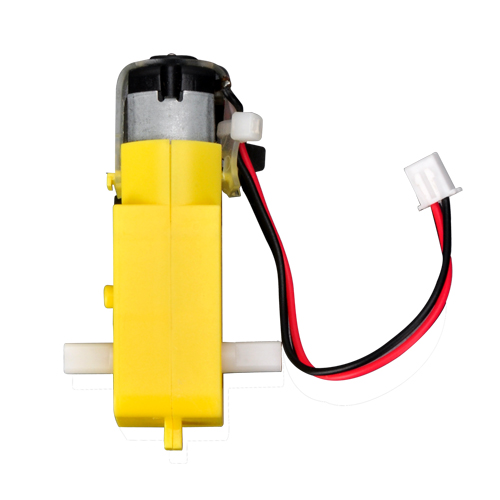
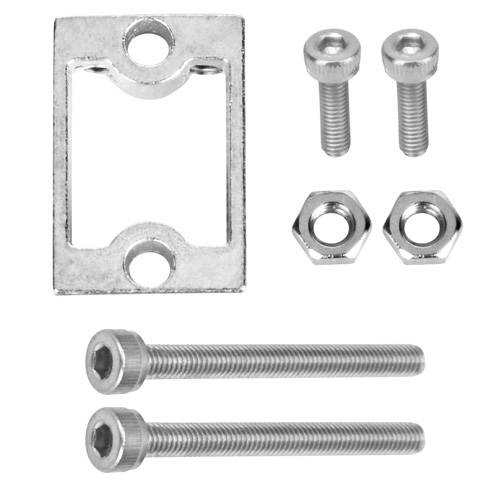
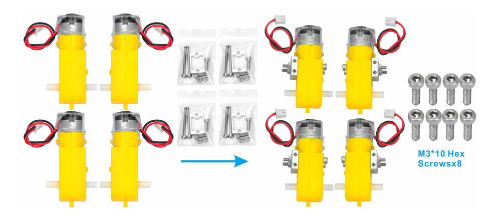
2) Attach 4 motors to the metal motor holders as shown below. (Check the motor direction before installing the metal motor holders.)
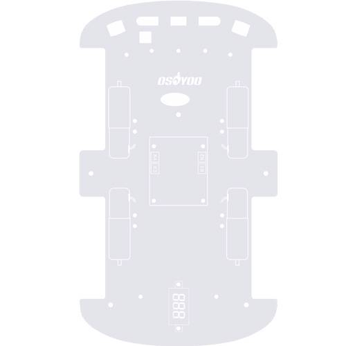
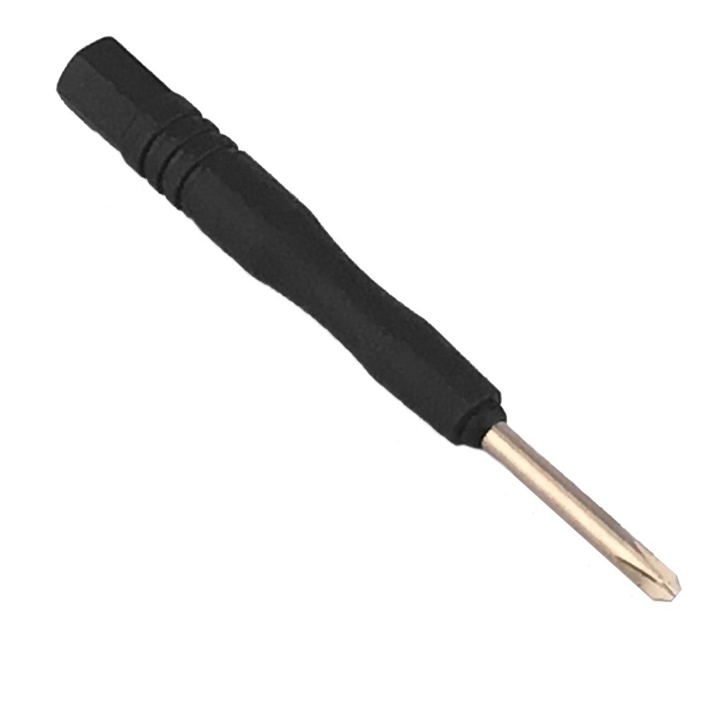
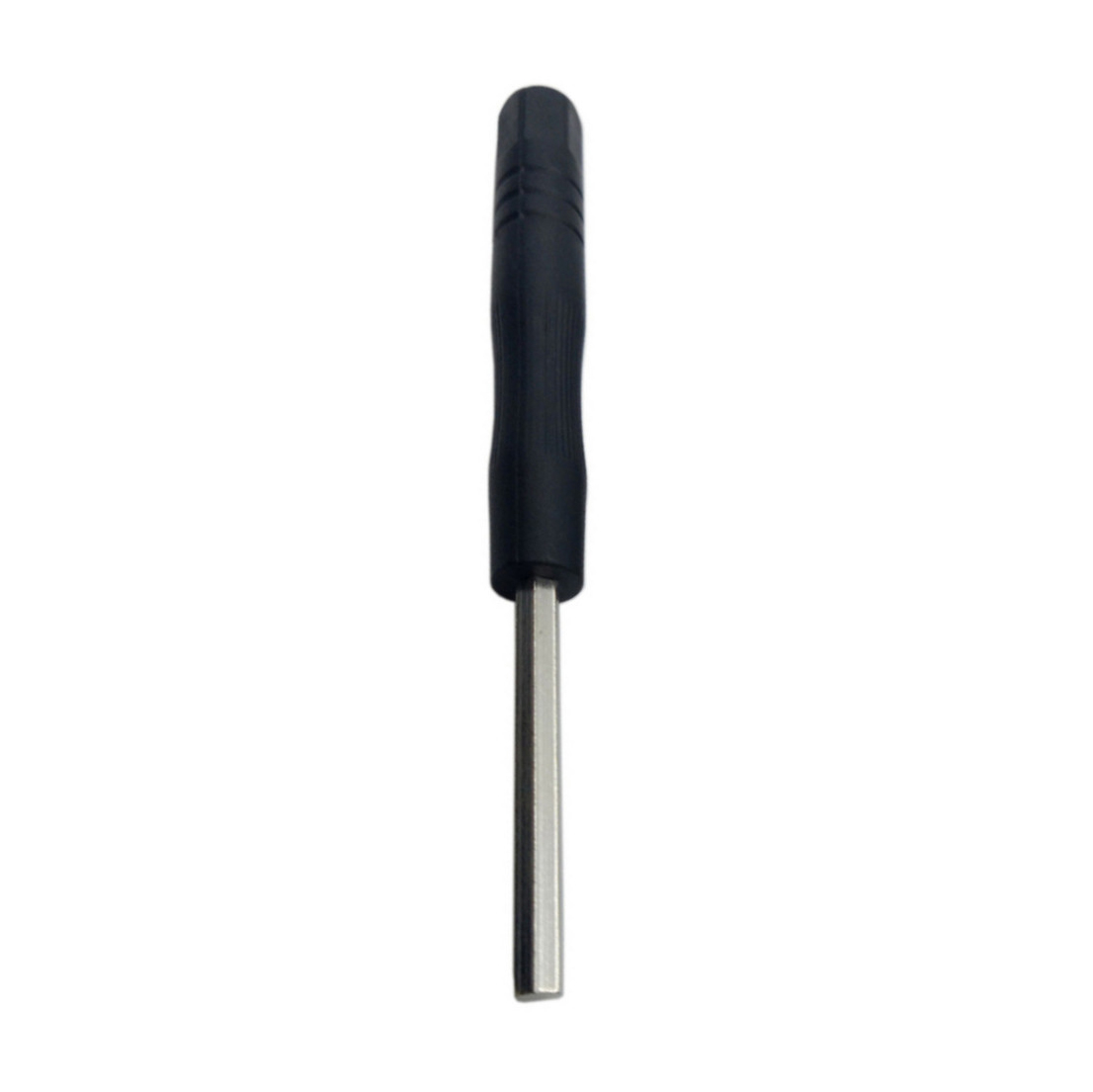
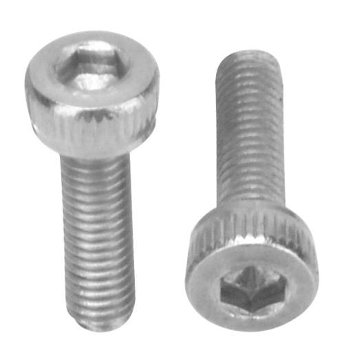
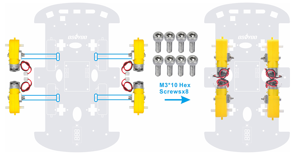
3) Mount the 4 motors onto the lower car chassis using M3*10 hex screws via a hex screwdriver. (The screws for this step are included in the metal motor holder package.)
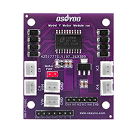
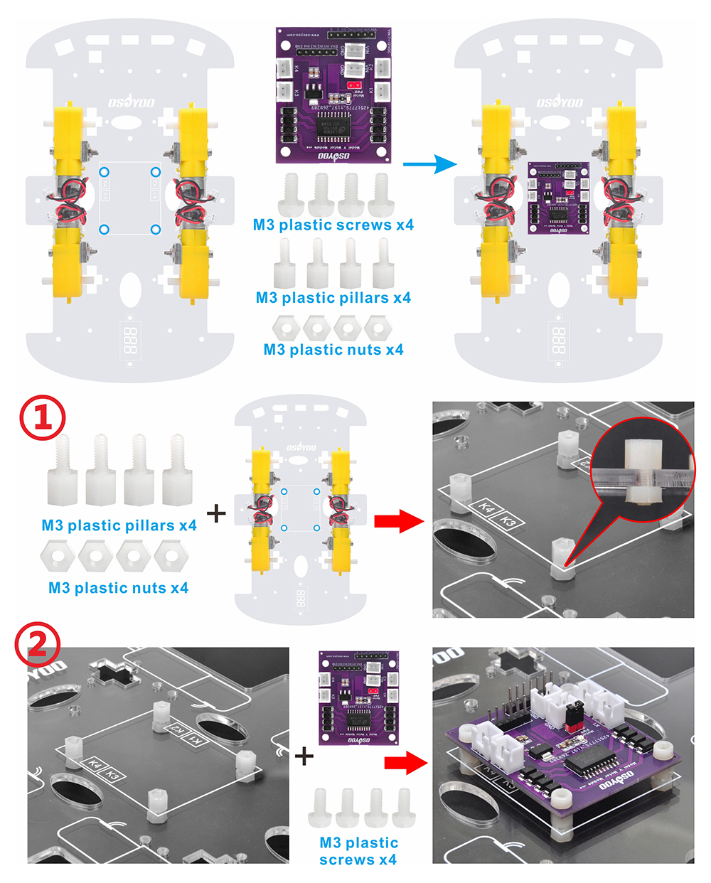
4) Install the OSOYOO Model V motor driver module onto the lower car chassis using 4 M3 plastic screws, plastic pillars, and plastic nuts. (Make sure the OSOYOO Model V motor driver module is installed in the correct direction.)
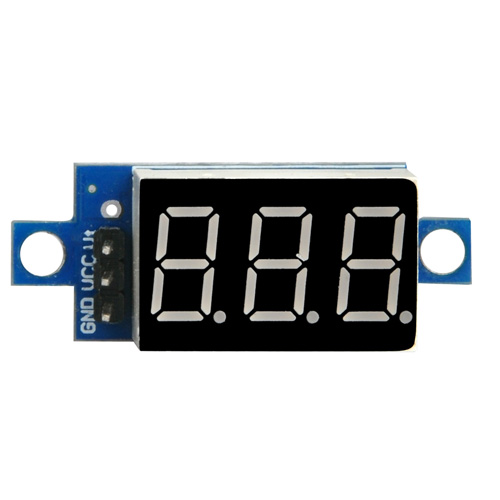
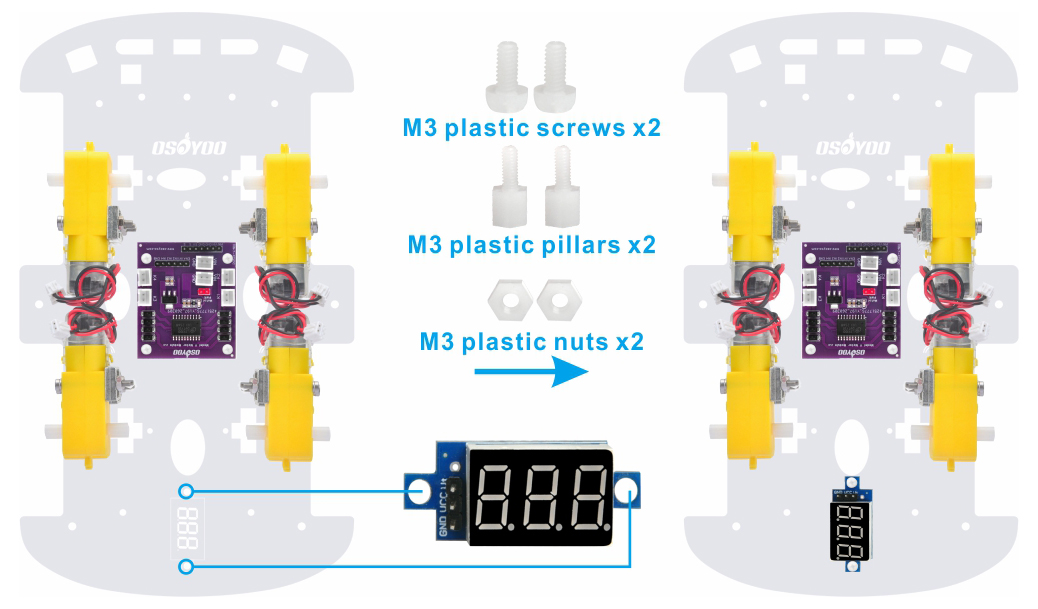
5) Mount the voltage meter on the lower car chassis using 2 M3 plastic screws, plastic pillars, and plastic nuts.
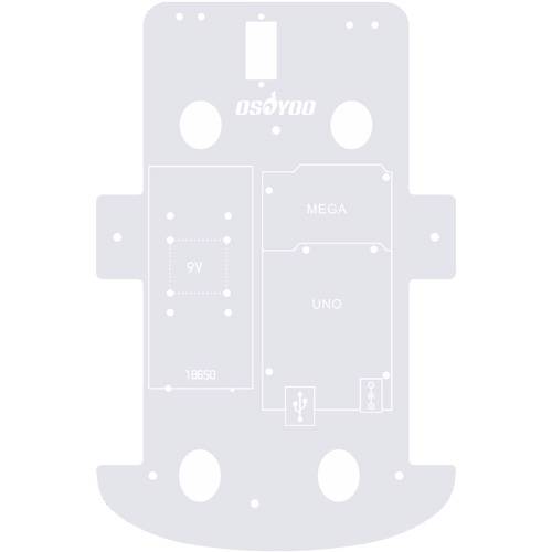
6) Mount the OSOYOO basic board on the upper car chassis using 4 M3 plastic screws, plastic pillars, and plastic nuts. (Install the board on the side with the printing.)
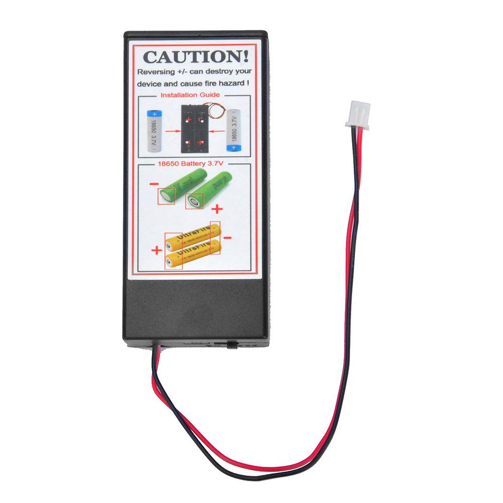
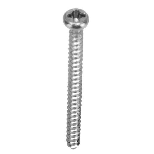
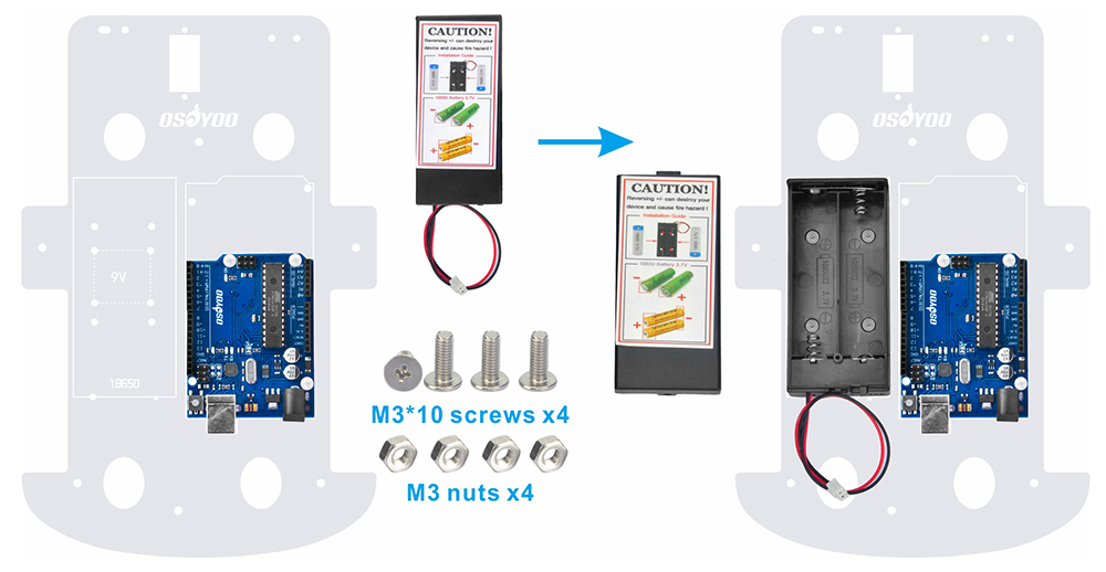
7) Fix the battery box onto the upper chassis using 4 M3*10 screws and M3 nuts.
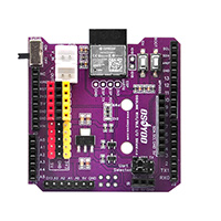
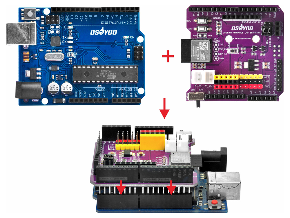
8) Plug the OSOYOO WiFi/BLE I/O shield onto the OSOYOO basic board.
Connections
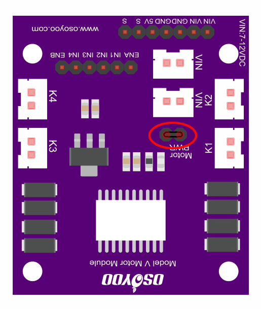
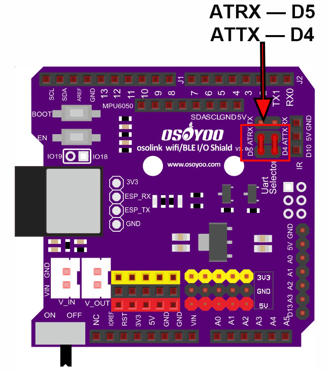
0) Confirm the jumper cap settings on the OSOYOO Model V motor shield and OSOYOO WiFi/BLE I/O shield as shown below (default settings).
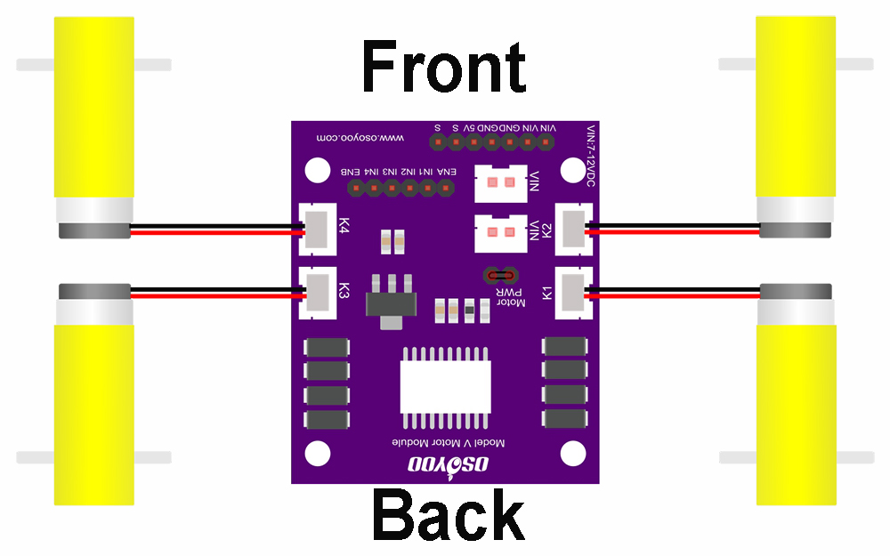
1) Connect the 4 motors to the OSOYOO Model V motor shield K1 to K4 sockets as shown in the diagram below.
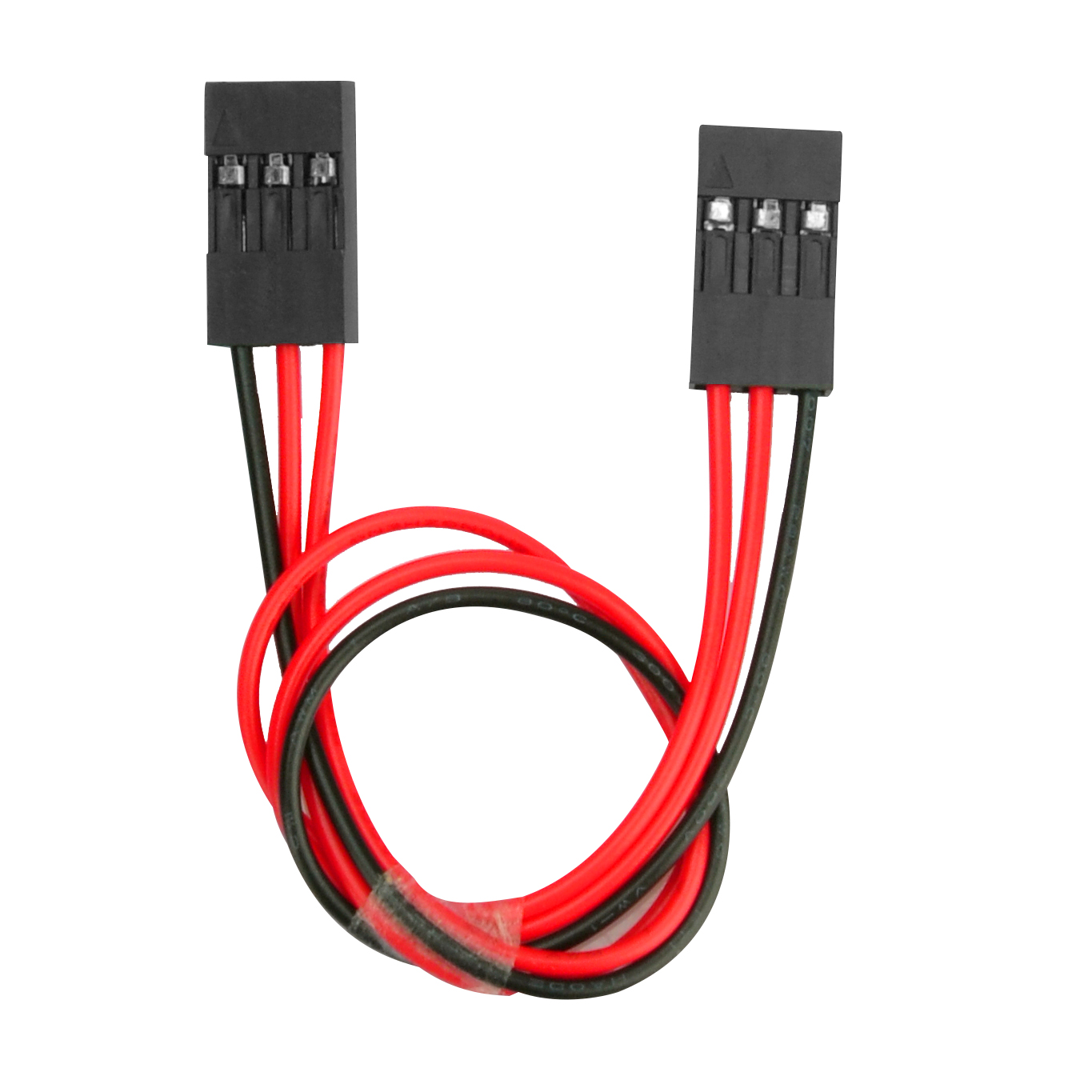
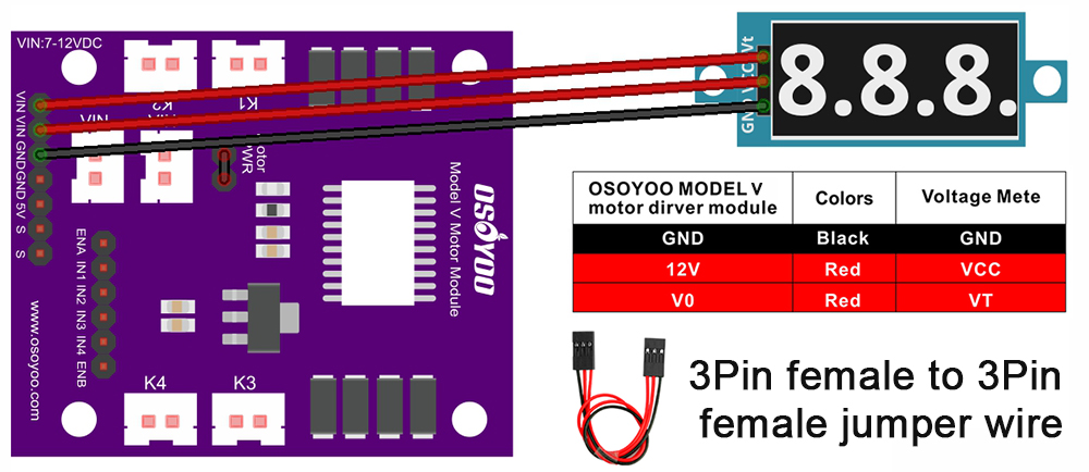
2) Connect the voltage meter to the OSOYOO Model V motor shield using the 3-pin female-to-female jumper wire as shown in the connection diagram below.
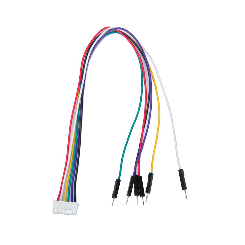
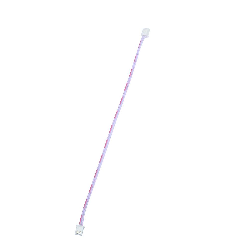
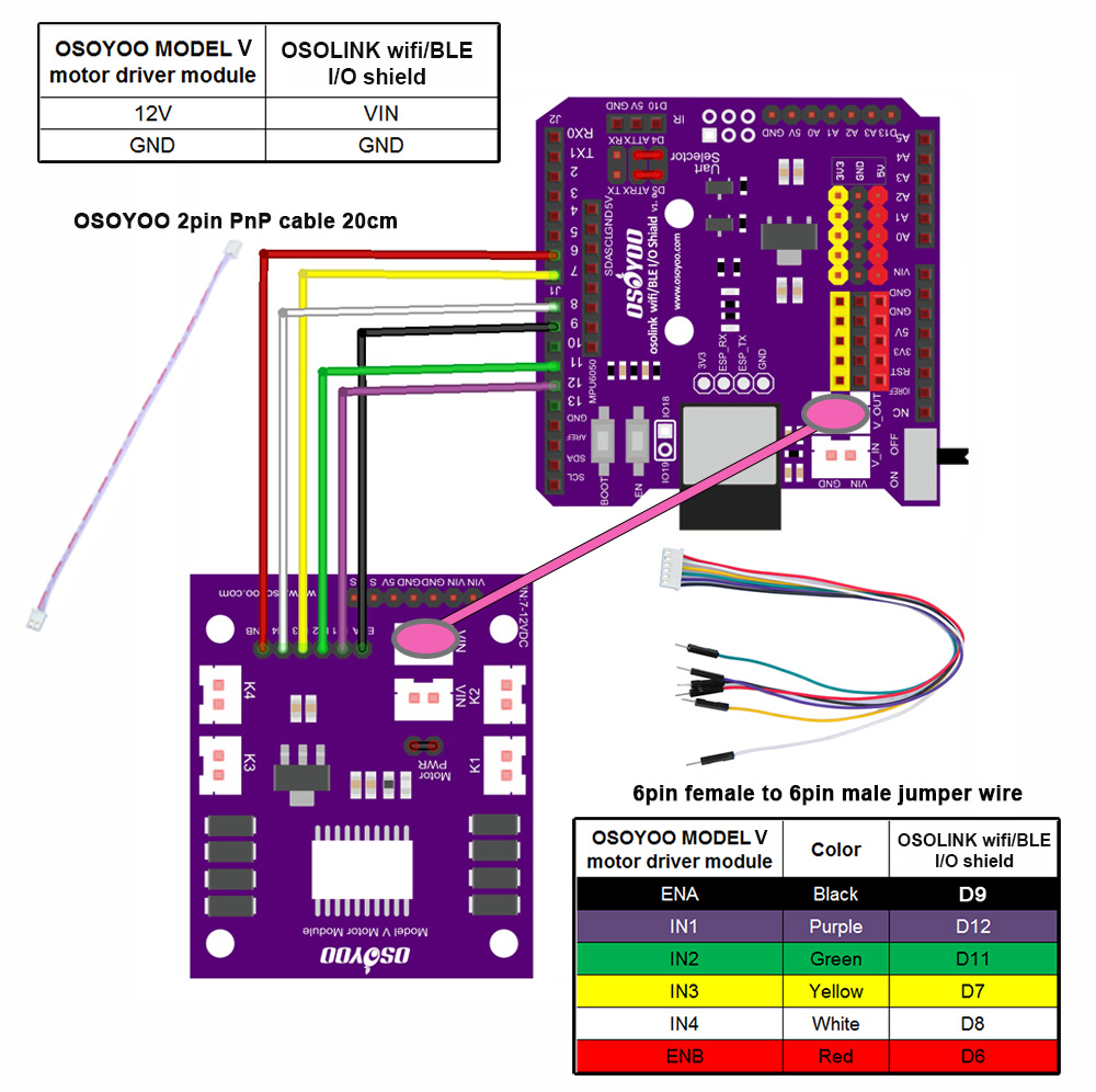
3) Connect the 6 control pins of the OSOYOO Model V motor shield to D6, D7, D8, D9, D11, D12 on the OSOYOO WiFi/BLE I/O shield using the 6-pin male-to-female jumper wire. Also connect the 12V-GND (VIN) socket to the VIN-GND (V_OUT) socket using the OSOYOO 2-pin PnP cable (20 cm), as shown in the diagram below. Caution:
When inserting or removing the 6-pin plug from the Model V 6-pin male socket, hold the plastic connector housing. Never pull the plug out by the wires — this will damage them.
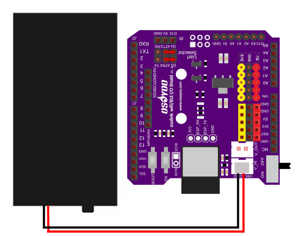
4) Connect the battery box to the VIN-GND (V_IN) socket of the OSOYOO WiFi/BLE I/O shield as shown in the connection diagram below.
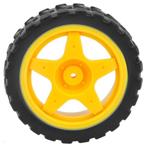
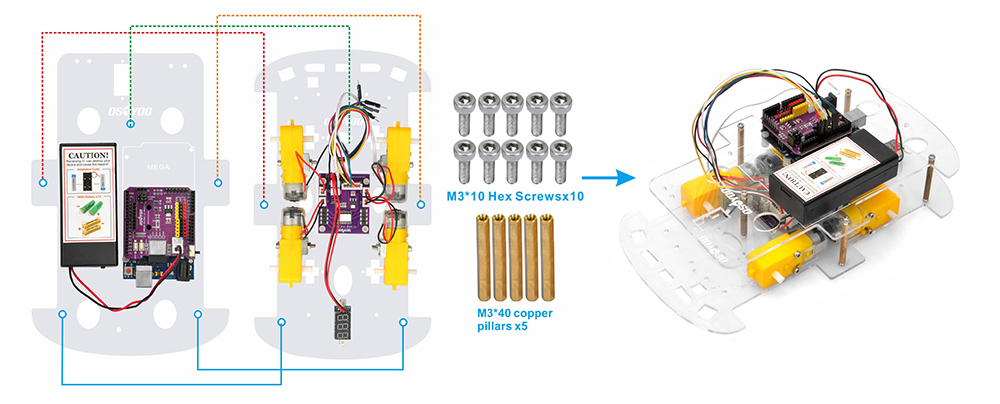
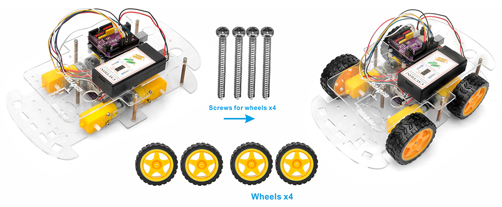
5) Join the upper chassis to the lower chassis using five copper pillars, and secure them with 10 M3*10 hex screws. Then install the 4 wheels onto the motors. (Loosen the wheel screws if any wheel does not turn freely.)
Hardware assembly is almost done. Before inserting the 18650 batteries, you need to upload the sample code to the board first.
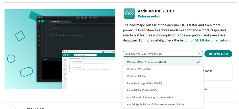
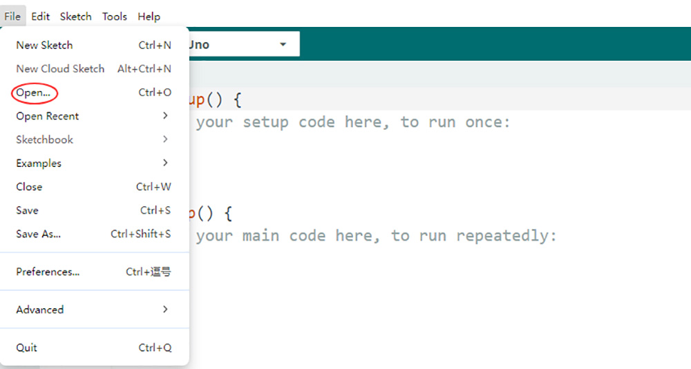
2. Download the sample code: Download the sample code for Lesson 1 from here. Extract the archive to get v3car-lesson1.ino inside the folder v3car-lesson1. Open the sketch in the Arduino IDE.
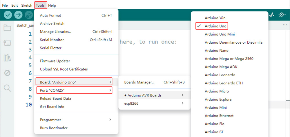
3. Select the board and port: Connect the OSOYOO basic board (compatible with Arduino UNO) to your computer via a USB cable. Important: make sure the robot car’s power switch is OFF and the battery is disconnected before connecting the board to your PC. In the Arduino IDE, go to Tools > Board and select Arduino Uno. Then go to Tools > Port and select the correct serial port. If you are not sure which port to choose, check Device Manager on Windows.
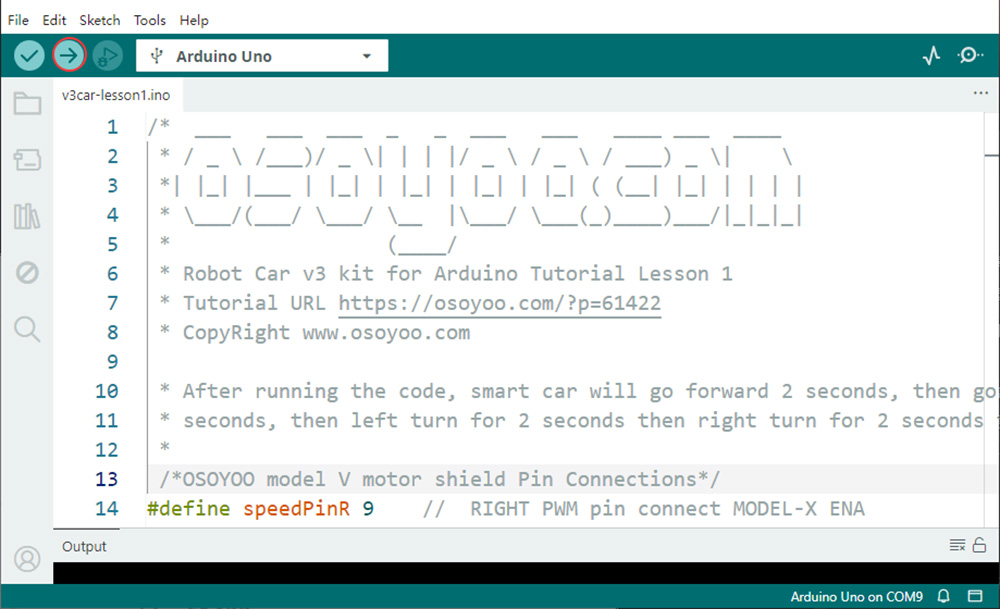
4. Upload the code: Click the Upload button (the right-arrow icon) to compile and upload the sketch to the OSOYOO basic board.
5Functional Testing and Verification
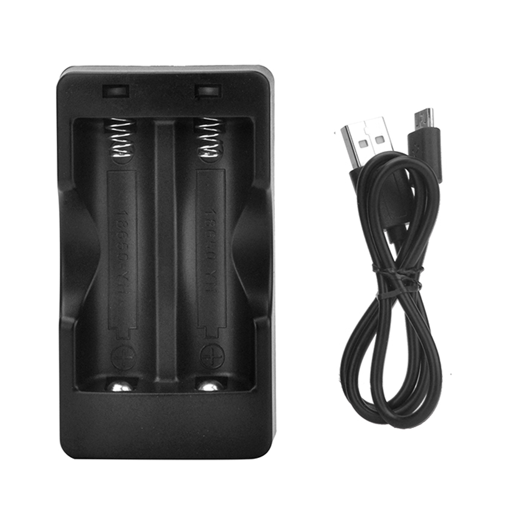
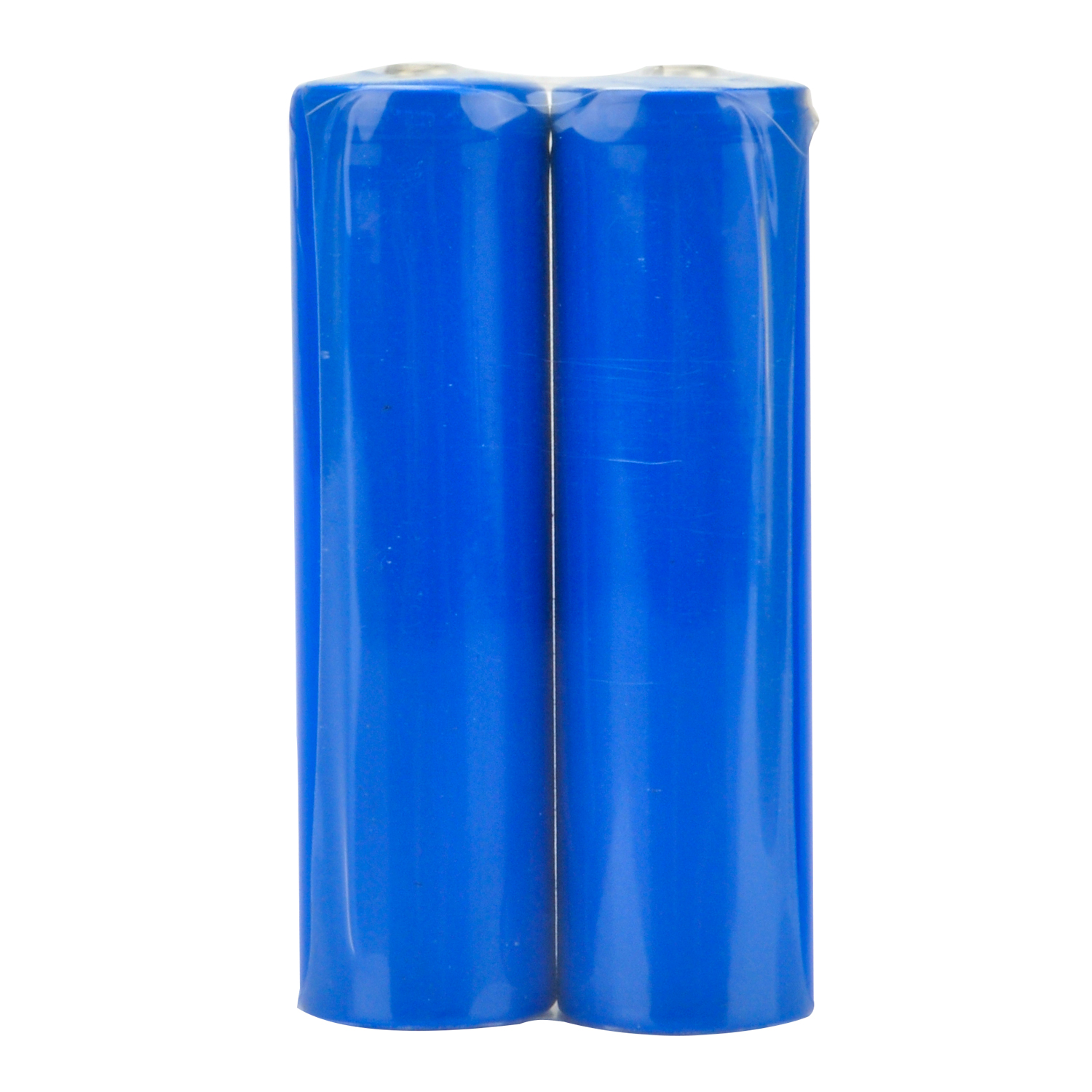
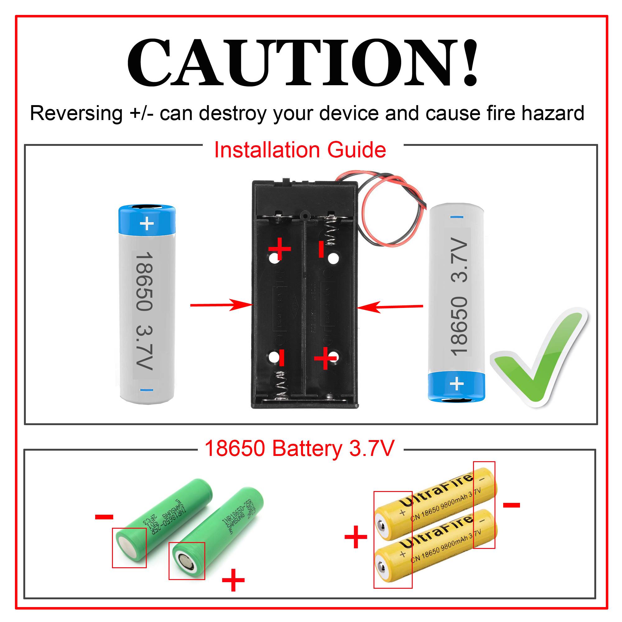
Note: 1) We recommend 18650 batteries — they provide smooth, reliable power for the robot car. 2) The 18650 batteries used in these lessons are approximately 65 mm (2.56 in) long and do not have an internal protection circuit. 3) Check the battery box label and make sure the polarity is correct. Reversed polarity can damage your device and may cause a fire hazard. After uploading the code successfully, disconnect the OSOYOO basic board from the PC. Insert the 18650 batteries into the battery box, observing correct polarity.
Place the robot car on a flat surface and turn on both switches on the battery box and OSOYOO WiFi/BLE I/O shield. The robot car should run a predefined sequence of movements:
Move forward for 2 seconds
Move backward for 2 seconds
Turn left for 2 seconds
Turn right for 2 seconds
Stop
If the robot car does not behave as expected, refer to the troubleshooting section below.
6Motor Control Logic
The OSOYOO Model V motor shield uses an H-bridge circuit to control the direction and speed of the DC motors. Understanding this logic is essential for more advanced programming.
Input Pins
Logic Level (IN1/IN2 or IN3/IN4)
Motor Group
Direction
IN1 / IN2
LOW / HIGH
K1 / K2
Backward
IN3 / IN4
HIGH / LOW
K3 / K4
Forward
IN3 / IN4
LOW / HIGH
K3 / K4
Backward
IN1 / IN2
HIGH / LOW
K1 / K2
Forward
• Speed Control: The ENA and ENB pins, connected to PWM-capable digital pins on the Arduino, control the speed of motor groups K1/K2 and K3/K4. By varying the PWM duty cycle, the effective voltage to the motors changes, adjusting their speed.
• Pin Mapping: ENA, ENB, IN1, IN2, IN3, and IN4 on the motor shield are connected to digital pins D9, D6, D12, D11, D7, and D8 on the Arduino via jumper wires.
7Troubleshooting
1. Motors Not Moving / Intermittent Movement:
Power supply: Check that the battery voltage is above 7.2 V. Recharge or replace batteries if necessary. Make sure both switches are in the ON position.
Wiring: Double-check all motor and power connections for correct polarity and firm seating.
Motor shield seating: Make sure the 6 control pins of the OSOYOO Model V motor shield are firmly and correctly connected to the OSOYOO WiFi/BLE I/O shield, with all pins aligned. If needed, replace the 6-pin jumper cable with six individual female-to-female jumper wires.
Motor check: If only one motor is not working, swap it with a known-good motor to determine whether the motor itself is defective.
Tips: How to test and troubleshoot motor issues using 3 jumper wires
Suppose your right motor cannot rotate, or it can only rotate backward but not forward. The cause is likely a wiring issue, though there is a very small chance that the Model X board or the motor itself is faulty.
To perform further testing:
Disconnect the 6-pin cable from the Model X board.
Based on the Motor Control Logic, use 3 single jumper wires to connect:
ENA to 5V
IN1 to 5V
IN2 to GND
If the motor can rotate forward, it means both the Model X board and the motor are working fine, and the issue lies in the connection. Reconnect the 6-pin cable. If it still doesn’t work, the 6-pin cable itself might be defective. Try replacing it with 6 individual jumper wires (any color) to connect the Model X board to the Wi-Fi board, and the problem should be resolved.
If the motor fails to move no matter how you connect it (which is very rare), the Model X board might be defective. In this case, please contact the OSOYOO support team to get a replacement motor or board.
If your other motor doesn’t rotate, please follow the same logic to figure out the problem.
2. Incorrect Movement Direction:
If the robot moves in the wrong direction, check that the red and black motor wires are soldered correctly on all motors, and make sure the 6 control pins of the OSOYOO Model V motor shield are correctly connected to the OSOYOO WiFi/BLE I/O shield.
3. Arduino IDE Connection Issues:
Driver installation: Make sure the correct USB-to-serial drivers for your Arduino board are installed.
Port selection: Confirm the correct COM port is selected in the Arduino IDE. On Windows, you can check Device Manager under “Ports (COM & LPT)”.
If none of the above resolves your issue, email us at [email protected] or leave a comment below this tutorial. Our tech support team will help you.