


| Buy from US |
Buy from UK |
Buy from DE |
Buy from IT |
Buy from FR |
Buy from ES |
ここでご購入を! |
 |
 |
 |
 |
 |
 |
 |
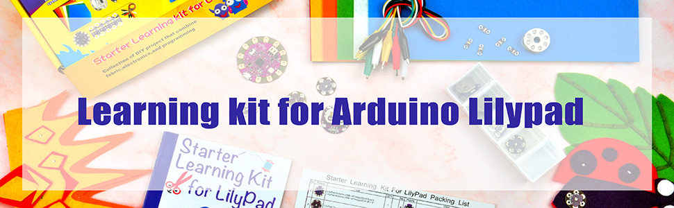
Introduction
In this project we’ll make musical melodies using a LilyPad USB board and a LilyPad Buzzer. You need to program the code into the LilyPad USB board. We’ll sew the LilyPad components onto felt and customize the theme and decoration.
Materials & Tools
• 1x LilyPad USB Board
• 1x LilyPad Buzzer
• 1x LilyPad Battery Holder or Battery Box with Connector
• Conductive Thread and Needle
• Music Buzzer Template
• Felt (use scraps of felt to add decorations)
• Embroidery or Sewing Thread

~~~~~~~~~~~~~~~~~~~~~~~~~~~~~~~~~~~~~~~~~~~~~~~~~~~~~~~~~~~~~~~~~~~~~~~~~~~~~~~~~~~~~~~
~~~~~~~~~~~~~~~~~~~~~~~~~~~~~~~~~~~~~~~~~~~~~~~~~~~~~~~~~~~~~~~~~~~~~~~~~~~~~~~~~~~~~~~
How to Make
Planning Your Project
For this project, we’ll be using the LilyPad music buzzer template. Download and print the template from our website (http://osoyoo.com/?p=13940).
Inside the buzzer is a coil of wire and a small magnet. When current flows through the coil, it becomes magnetized and is pulled toward the magnet, which makes a tiny “click.” When this happens thousands of times per second, the clicks create tones. We can use commands in Arduino to click the buzzer at specific frequencies, which we hear as different pitches.
Understanding Your Circuit
In this project, you will need three LilyPad pieces: the LilyPad USB board, the LilyPad Buzzer, and a LilyPad Coin Cell Battery Holder or AAA battery box.
The LilyPad USB board can also be powered by a small battery or an AAA battery box with a JST XH Connector. If you don’t want to sew the battery holder into this project, you can plug the AAA battery box’s white connector into the LilyPad USB board’s white connector. Make sure you align the notch on the battery connector with the matching notch on the board’s connector.
Stitching It Together
Step 1:
Begin by stitching tab (2) on the LilyPad USB board to the tab (+) on the LilyPad Buzzer with three loops at each tab. Tie and cut.
With a new piece of conductive thread, sew three loops around tab (+) on the LilyPad USB board to the tab (+) on the LilyPad Battery Holder, making three loops at each tab. Tie and cut.


Step 2:
Next, stitch to connect Tab (−) of the LilyPad USB board to Tab (−) of the battery holder. Tie and cut.
With a new piece of thread, sew three to four loops around Tab (−) of the LilyPad Battery Holder, then continue stitching to connect Tab (−) of the LilyPad Buzzer. Tie and cut.


Uploading an Arduino Sketch
Step 1: Open Arduino IDE
In Lesson 4, you installed the Arduino IDE on your computer. Click the desktop icon to open the Arduino window.

Step 2: Connect to the LilyPad Board
Connect the LilyPad Arduino USB board to your computer with a USB data cable. When the switch is in the ON position, the microcontroller receives power and the board runs.

Before uploading code, check a few settings. Make sure “Board” is set to “LilyPad Arduino USB” and “Port” is set to “LilyPad Arduino USB.” Then select “USBtinyISP” from Tools > Programmer.
Step 3: Upload the Code
Download the example code for this tutorial. Open it, then upload the code by clicking the right-pointing arrow button. Give Arduino a few seconds to compile the code, then a few more to upload. The code below is provided for reference.
Click here to download: Project5_music_buzzer.zip
Installing Your Battery and Testing
Insert the coin cell battery into the LilyPad USB board’s battery holder with the positive (+) side facing up. Press the power button on the LilyPad USB board — the LilyPad Buzzer will play a simple song. If it works, remove the battery and continue to the Finishing Touches section.

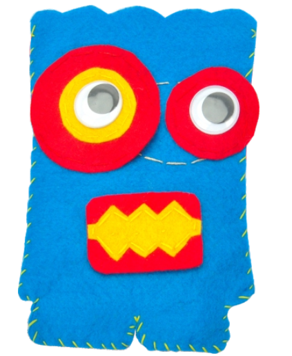
Finishing Touches
After verifying that the circuit works, it’s time to customize your project. Adding felt over the LilyPad pieces can hide the boards. Using non-conductive sewing or embroidery thread, cover all but 2 inches at the right and left of the large circle. Leave those openings to plug in the battery box or USB cable.
~~~~~~~~~~~~~~~~~~~~~~~~~~~~~~~~~~~~~~~~~~~~~~~~~~~~~~~~~~~~~~~~~~~~~~~~~~~~~~~~~~~~~~~
Sewable Electronics Projects:
~~~~~~~~~~~~~~~~~~~~~~~~~~~~~~~~~~~~~~~~~~~~~~~~~~~~~~~~~~~~~~~~~~~~~~~~~~~~~~~~~~~~~~~


