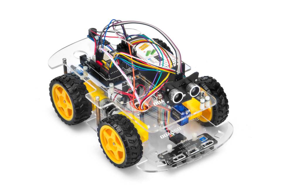
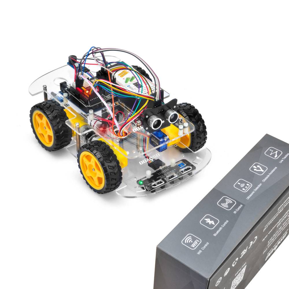
In this lesson, we will add a servo motor, an ultrasonic module and a buzzer onto Lesson 1 framework. With these new devices, the car can “see” obstacle through ultrasonic sensor and measure the distance. If the distance is less than predefined threshold value, the buzzer will beep and the car will turn around from the obstacle automatically.
Step 1: Install the smart car basic frame work as per Smart Car Lesson 1 .If you have already completed installation in Lesson 1 , Everything keep it as is except move ENA from D9 to D3(we need D9 for Servo control). If you have installed Lesson 2 or 3, you have to remove the wires. If you have installed Lesson 4, you can keep it.
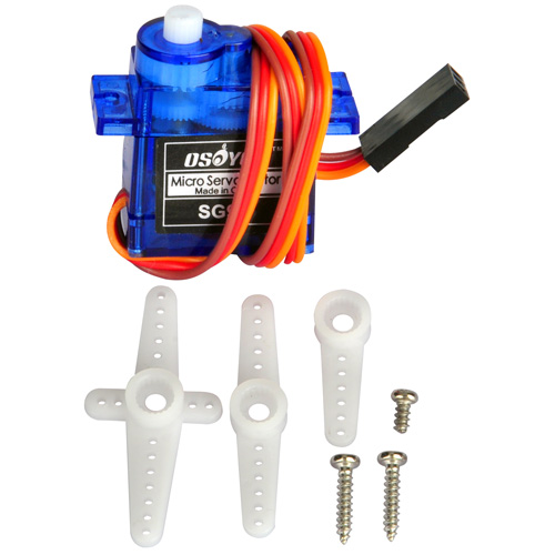
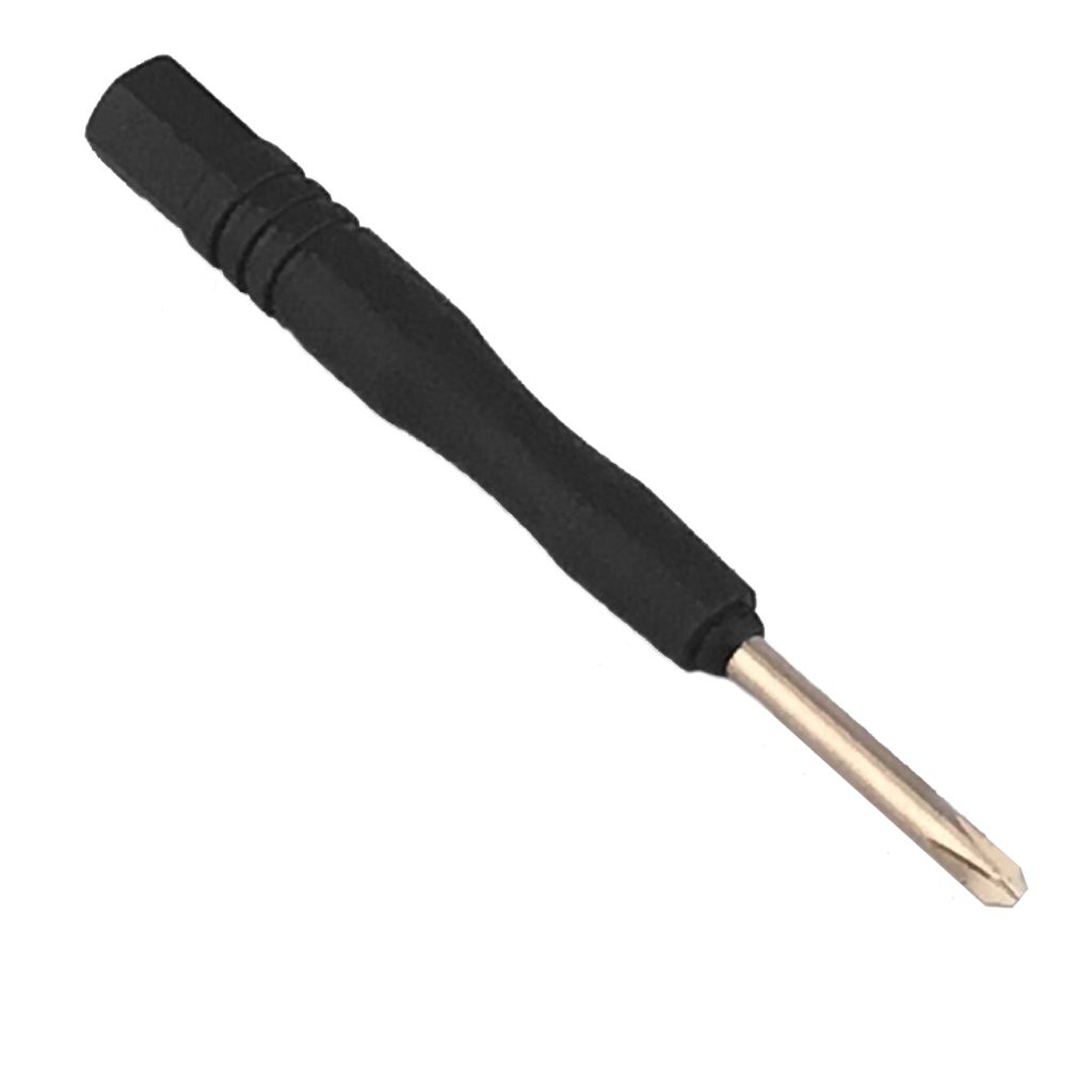
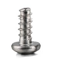
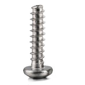
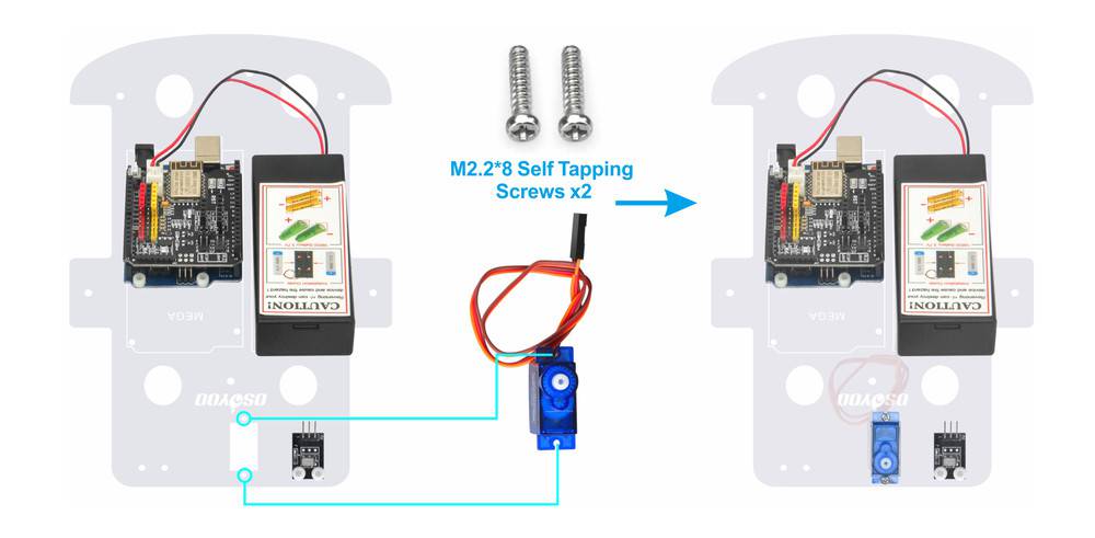
Step 2: Install servo motor at the front of upper car chassis with 2pcs M2.2*8 Self Tapping Screws
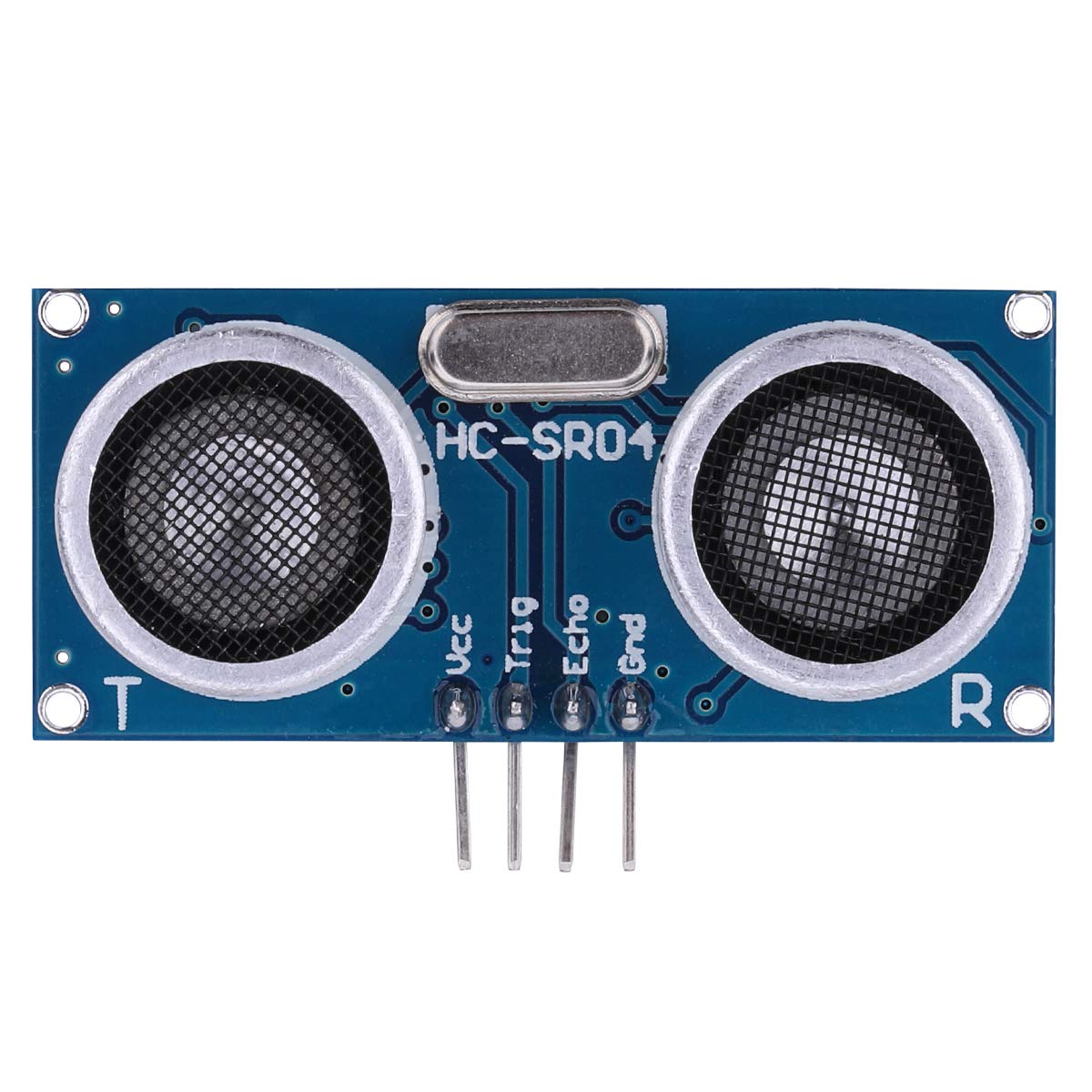
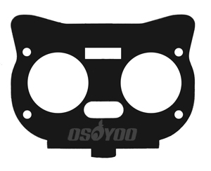
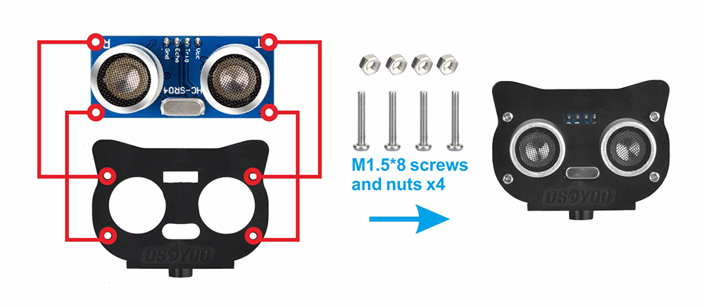
Step 3: Install Ultrasonic Module to mount holder with 4pcs M1.5*8 screw and M1.5 nuts
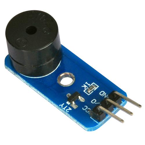
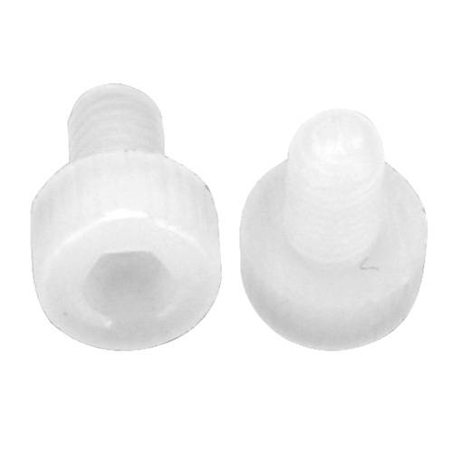
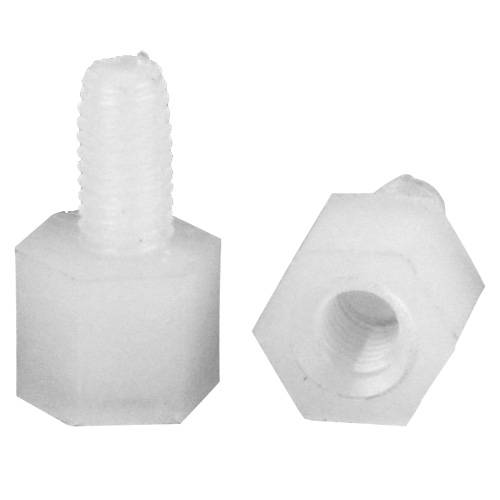
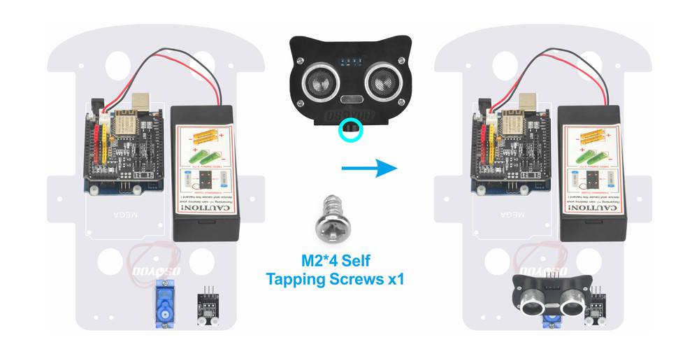
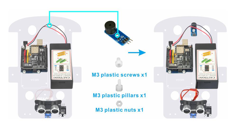
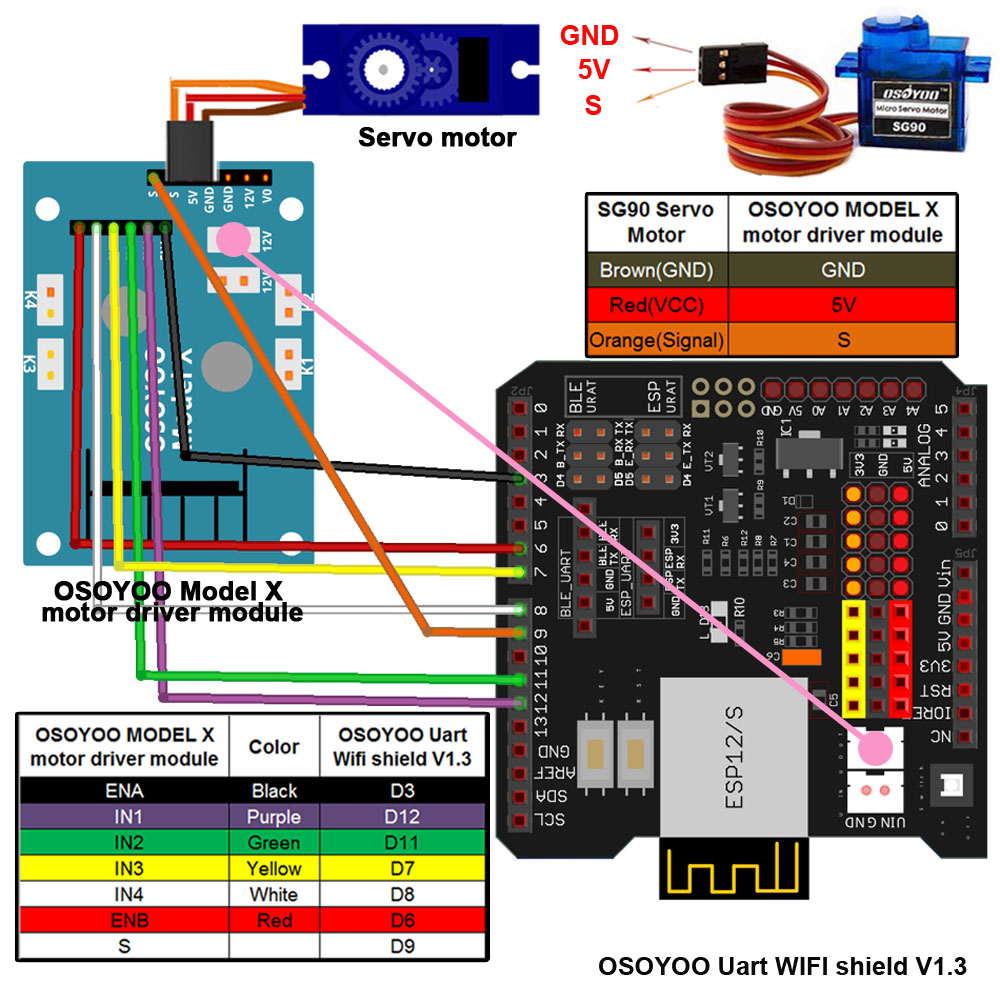
Step 4: Install mount holder for Ultrasonic Module on servo motor with M2*4 Self Tapping screw Step 5: Install Buzzer module at the back of upper chassis with 1pc M3 plastic screw, M3 plastic pillar and M3 plastic nut Step 6: Connect SG90 servo motor, OSOYOO MODEL X motor driver module and OSOYOO Uart WiFi shield V1.3 as following grape:
Note: As the limited Digital signal pins, you need to remove some wires of previous lessons. If you have already completed installation in Lesson 1 , Everything keep it as is except move ENA from D9 to D3(we need D9 for Servo control). If you have installed Lesson 2 or 3, you have to remove the wires.
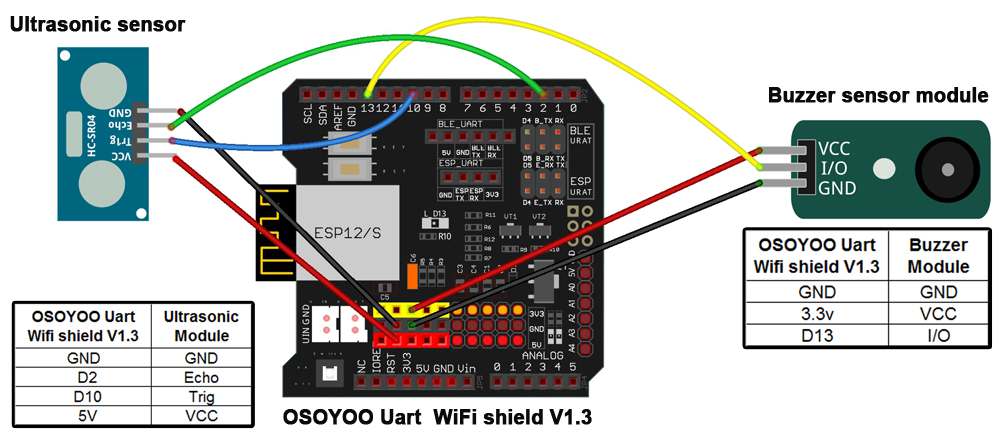
Step 7: Connect ultrasonic module, Buzzer module with OSOYOO Uart WiFi shield V1.3 as below connection diagram Step 8: Fix the screws on copper pillars to connect upper chassis to lower chassis if you remove these.
Step 1: Install latest Arduino IDE (If you have Arduino IDE version after 1.1.16, please skip this step). Download Arduino IDE from https://www.arduino.cc/en/Main/Software?setlang=en , then install the software.
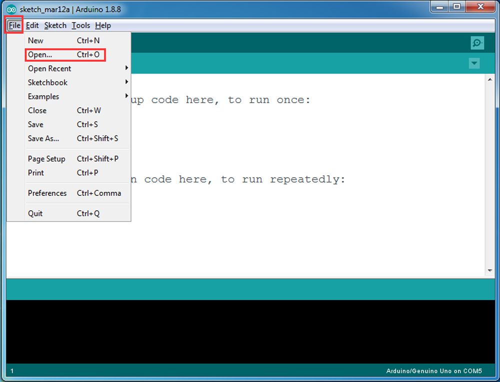
Step 3: Connect Arduino UNO to PC with USB cable, Open Arduino IDE -> click file -> click Open -> choose code “v2smartcar-lesson5.ino” in smartcar-lesson5 folder, load the code into arduino. (Notice: Please turn off battery power when your Robot is connected to Personal Computer or Laptop via USB cable)
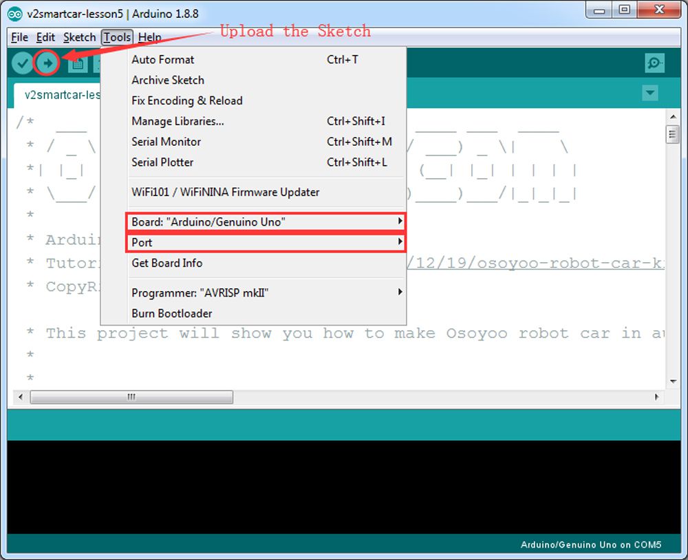
Step 4: Choose corresponding board/port for your project,upload the sketch to the board.
Step 5:Ultrasonic sensor servo initial direction alignment
After turning on the battery, you will hear a long beep sound, then the servo will make some movement and finally stops at a direction for 5 seconds.
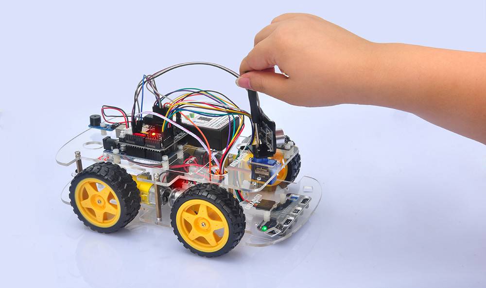
During this first 5 seconds, you must make sure the Ultrasonic sensor(two eyes) is facing straight forward.
If it is not straight forward, you should turn off battery immediately and remove the sensor from servo, reinstall it and make it facing straight forward direction as following picture. Otherwise the obstacle avoidance program will not work properly.
After adjusting sensor direction, turn on battery again. After hearing the long beep, the sensor should face front same as following picture. If its direction is not straight forward, turn off battery and do direction alignment again.
Final Testing :
After Turning on the battery switch on the battery box, if the ultrasonic module turn to front view position, that means you no need adjust sensor position anymore. Just wait 5 seconds. If no obstacle is detected, the car will go forward. If any obstacles is detected, the car will stop, the ultrasonic module will turn from right to left to detect surrounding obstacle. The robot car will decide to make left turn, right turn or backward according to obstacle sensor data and our obstacle avoidance algorithm.
Sometimes your car might have collision and make your Ultrasonic sensor position change, you must remember to do sensor direction alignment again as per link Ultrasonic sensor servo initial direction alignment
Step 2) Unzip above file and run the servo.ino file in your car.
Your servo will move from left to right and finally stop to center position. If your ultrason sensor is not facing to front direction. Please release your ultrasonic sensor from servo head, re-position its direction to front , then fasten the sensor screw to fix its direction. See video from 7:4 to 8:10
Step 3) After you have changed the sensor direction, please run v2smartcar-lesson5.ino sketch again. Your car will begin to do obstacle avoidance driving.
You can change the following code to adjust the speed:
#define BUZZ_PIN 13
#define FAST_SPEED 250 //both sides of the motor speed
#define SPEED 120 //both sides of the motor speed
#define TURN_SPEED 200 //both sides of the motor speed
#define BACK_SPEED1 255 //back speed
#define BACK_SPEED2 90 //back speed
How to make the car not to stop every LPT cycle and let it move continously. I delete every stop_Stop function from the watchsurround function but it still does it? Please I need help. Thanks
After the robot car is stopped, it detects whether there are obstacles in different directions through the servo and ultrasonic sensors, so that the robot can bypass the obstacles on its way forward.
Hi, when I want to move the black wire from D9 to D3, I see that D3 is taken by another wire, specifically the Out (left) wire of the IR Obstacle Avoidance Module from lesson 3. Where should I move the black wire?
Hi Elaine,
Lesson 5. I have removed wires from Lessons 2 & 3.
The robot only moves 3 or 4cms at a time but does not run when well away fro object. I have reduced te distance in the code to 10 but this has not made any difference. What is my problem?
Jim.
What do you mean “The robot only moves 3 or 4cms at a time but does not run when well away fro object” ? Can you send a short video about your current running result. our support email is [email protected]
Hi John,
I have been trying for several days to send you a short video but I am unable to make it short enough to be accepted by the email serrvice. So I will try to explain what is happening.
When switched on in an open space in a room , minimum of one meter from an obstacle. The robot will do a scan of with the distance scanner then move forward about 4cms, that is about 3/4 turn of the wheels then move back slightly, turn slightly to right or left , then do the same again. More or less stayiong within the same square. I have reduced the minimum distance in the code to 10cms but this has made no difference. I would expect the robot , when switched on to move forward until it sees an object 10cms away, stop do a scan, back up, turn away and do another scan then proceed to go forward again etc. Am I expecting wrong?
Do you have Youtube account? Please upload the video to Youtube and send the link to us.
Do you mean the car will detect the object for long distance?
Please check whether the wires on Ultrasonic sensor? whether the echo and Trig are cross wrong?
buzzer might be defective. If you want , you can send your order number and address to [email protected] and ask for a new buzzer replacement. Actually buzzer is not quite important, you can keep doing other lessons without buzzer and test lesson 5 after you get new buzzer.
Hi Elaine,
the car behaves strangely. It measures the distance to an obstacle correctly and shows it in the serial monitor, but it never goes forward. It either runs backwards or turns in circles.
How do you know the distance to obstacle showing correctly? If the aar always moving back or turning arround, it means the sensor didn’t send proper obstacle signal to Arduino. there is a simple way to test your ultrasonic sensor obstacle detection function is good or bad.
1)Run v2smartcar-lesson5.ino, do not turn on the battery, keep the USB cable connecting Arduino board and your computer. The car’s ultrasonic sensor will rotate but car won’t move.
2)Open Serial monitor , face the car to any direction which as obstacle(for example, your PC screen), then Serial monitor should show something like:
begin str=00100 or begin str=01100 , which tells that in center direction has some obstacles (0 stands for non-obstacle, 1 stands for obstacle , from left to right 5 digits means the obstacle situation from far left , left, center, right, far right).
If you face the car to an area which has no obstacle, it should show 00000 which means no obstacles in 5 directions, then car will move forward. However, if you got 11111 even your car has no obstacles in front, your sensor connection to Arduino must have some problem.


How to make the bot move faster instead of stopping every second?
You can change the following code to adjust the speed:
#define BUZZ_PIN 13
#define FAST_SPEED 250 //both sides of the motor speed
#define SPEED 120 //both sides of the motor speed
#define TURN_SPEED 200 //both sides of the motor speed
#define BACK_SPEED1 255 //back speed
#define BACK_SPEED2 90 //back speed
Elaine
How to make the car not to stop every LPT cycle and let it move continously. I delete every stop_Stop function from the watchsurround function but it still does it? Please I need help. Thanks
After the robot car is stopped, it detects whether there are obstacles in different directions through the servo and ultrasonic sensors, so that the robot can bypass the obstacles on its way forward.
I don’t know what your code looks like, and I don’t quite understand your purpose of doing this. Can you post your code?
It is normal for the Model X motor driver to flash when only Uno’s board is powered?
Please check the wiring and then check the battery status of the robot
Hi, when I want to move the black wire from D9 to D3, I see that D3 is taken by another wire, specifically the Out (left) wire of the IR Obstacle Avoidance Module from lesson 3. Where should I move the black wire?
Hi, you need to remove the wires of lesson2 and lesson3, when you test the lesson 4 and 5.
Can someone explain to me what this part of the code in the watch() function means?
digitalWrite(Trig_PIN,LOW);
delayMicroseconds(5);
digitalWrite(Trig_PIN,HIGH);
delayMicroseconds(15);
digitalWrite(Trig_PIN,LOW);
echo_distance=pulseIn(Echo_PIN,HIGH);
I think we need to measure the delay of the pulse to know the distance, but it looks like just measuring the pulse width which is fixed to be 15 μs.
Hi Elaine,
Lesson 5. I have removed wires from Lessons 2 & 3.
The robot only moves 3 or 4cms at a time but does not run when well away fro object. I have reduced te distance in the code to 10 but this has not made any difference. What is my problem?
Jim.
hi, James,
What do you mean “The robot only moves 3 or 4cms at a time but does not run when well away fro object” ? Can you send a short video about your current running result. our support email is [email protected]
Thanks
John @osoyoo support team
Hi John,
I have been trying for several days to send you a short video but I am unable to make it short enough to be accepted by the email serrvice. So I will try to explain what is happening.
When switched on in an open space in a room , minimum of one meter from an obstacle. The robot will do a scan of with the distance scanner then move forward about 4cms, that is about 3/4 turn of the wheels then move back slightly, turn slightly to right or left , then do the same again. More or less stayiong within the same square. I have reduced the minimum distance in the code to 10cms but this has made no difference. I would expect the robot , when switched on to move forward until it sees an object 10cms away, stop do a scan, back up, turn away and do another scan then proceed to go forward again etc. Am I expecting wrong?
Do you have Youtube account? Please upload the video to Youtube and send the link to us.
Do you mean the car will detect the object for long distance?
Please check whether the wires on Ultrasonic sensor? whether the echo and Trig are cross wrong?
The M2.2 * 8 screws do not actually attach the motor to the chassis, the chassis’s holes are too big so the motor just moves around
Hi Elaine
I have now reached Lesson 5. It works OK except the buzzer does not make sound. Wiring is OK
Any suggestions?
Regards, James.
buzzer might be defective. If you want , you can send your order number and address to [email protected] and ask for a new buzzer replacement. Actually buzzer is not quite important, you can keep doing other lessons without buzzer and test lesson 5 after you get new buzzer.
Hi Elaine,
Thanks fort your attention. I will not bother with the buzzer. I have now completed all lessons.
Regards, James.
olá eu montei o carrinho todo mas quando ligo o senssor ultrassonico ele começa a dar um beep constatente sem parar o que que eu faço?
you can remove that buzzer. it is not a necessary part.
Hi Elaine,
the car behaves strangely. It measures the distance to an obstacle correctly and shows it in the serial monitor, but it never goes forward. It either runs backwards or turns in circles.
How do you know the distance to obstacle showing correctly? If the aar always moving back or turning arround, it means the sensor didn’t send proper obstacle signal to Arduino. there is a simple way to test your ultrasonic sensor obstacle detection function is good or bad.
1)Run v2smartcar-lesson5.ino, do not turn on the battery, keep the USB cable connecting Arduino board and your computer. The car’s ultrasonic sensor will rotate but car won’t move.
2)Open Serial monitor , face the car to any direction which as obstacle(for example, your PC screen), then Serial monitor should show something like:
begin str=00100 or begin str=01100 , which tells that in center direction has some obstacles (0 stands for non-obstacle, 1 stands for obstacle , from left to right 5 digits means the obstacle situation from far left , left, center, right, far right).
If you face the car to an area which has no obstacle, it should show 00000 which means no obstacles in 5 directions, then car will move forward. However, if you got 11111 even your car has no obstacles in front, your sensor connection to Arduino must have some problem.
Hope this helps.