Welcome to the first lesson of OSOYOO Servo Steer Smart Car for Raspberry Pi!
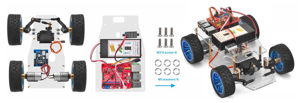
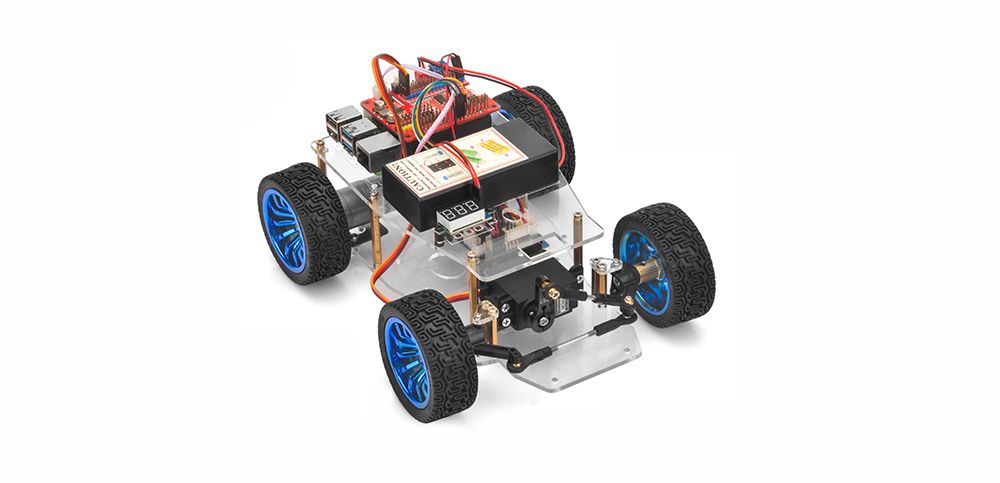
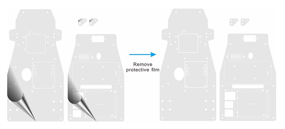
In this lesson, we will install the framework of the OSOYOO Servo Steer Smart Car for Raspberry Pi and simply instroduce the hardware of this robot.
All lessons are based on the frame work of this lesson. Please follow this lesson carefully.
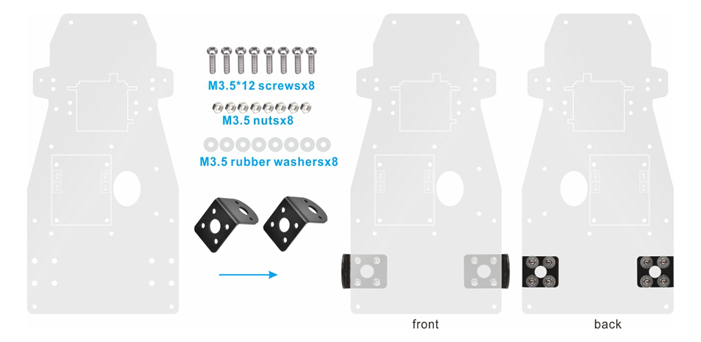
2. Fix motor holders on the lower chassis with 8pcs M3.5*12 screws, M3.5 nuts and M3.5 rubber washers. From top to bottom, use M3.5*12 screws cross lower chassis, Motor holder, 3.5 rubber washer and then 3.5 nut as follow:
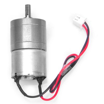
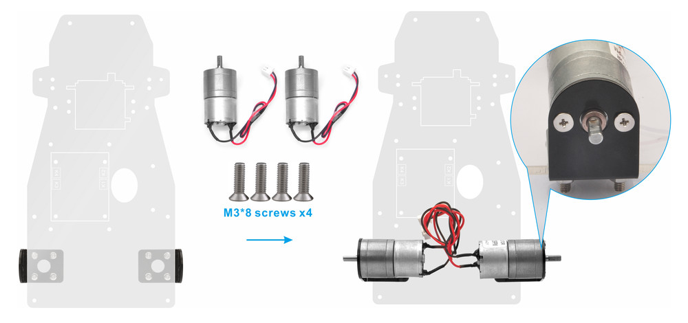
3. Cross motor holder, use M3*8 screws to fix motor on motor holder as follow:
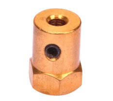
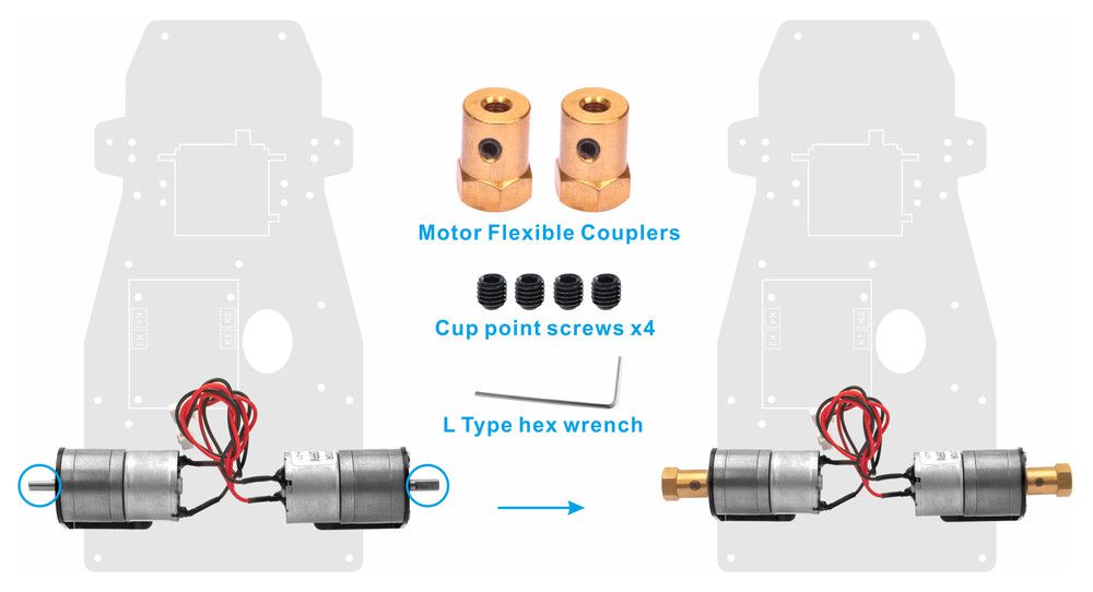
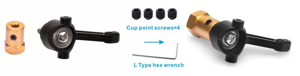
4. Install motor flexible couplers on motors and use cup point screws to fix motor flexible couplers on motor.
The shaft from the motor has a flat area on it. Make sure that cup point screws are positioned on this flat, and tightened both screws on the shaft.
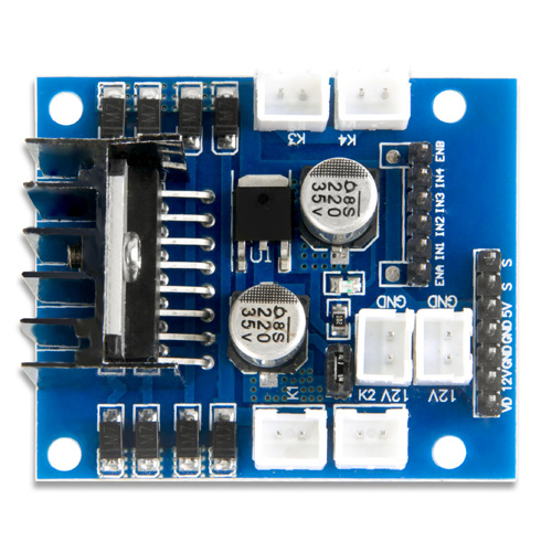
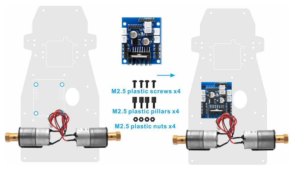
5. Install OSOYOO MODEL X motor driver module to lower car chassis with 4pcs M2.5 plastic screws, plastic pillars and plastic nuts. (Please make sure you install the OSOYOO MODEL X motor driver module in correct direction.)
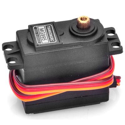
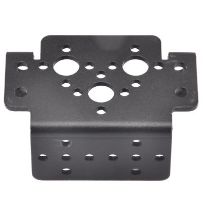
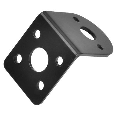
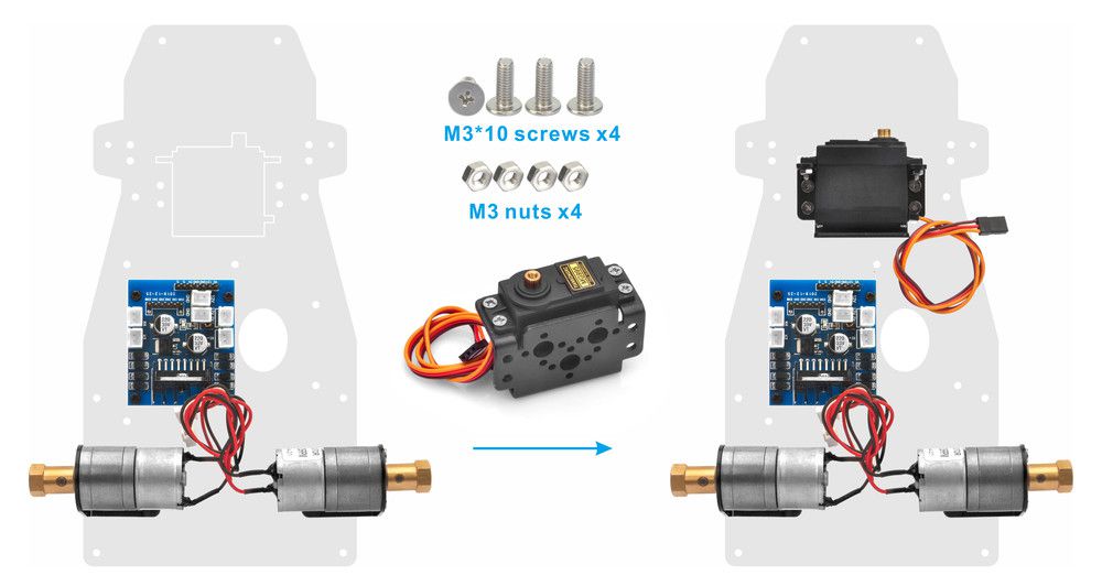
6. Fix servo motor on servo motor holder with M3*10 screws and nuts as follow:
7. Use M3*10 screws cross servo motor holder with servo motor, lower chassis and nut to fix servo motor on lower chassis as follow:
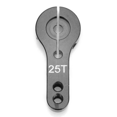
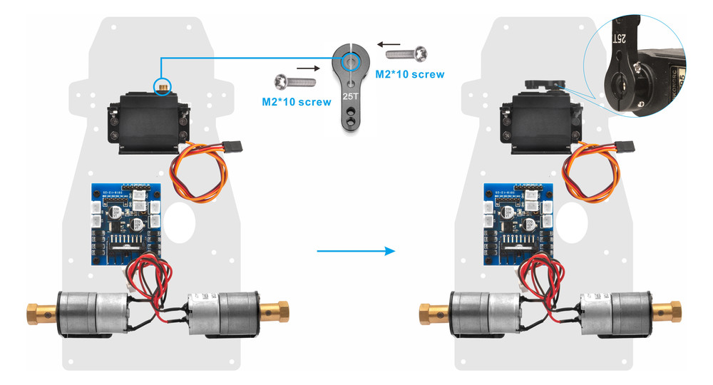
8. Install servo horn on servo motor and install M2*10 screw on the each sides of servo horn as follow:
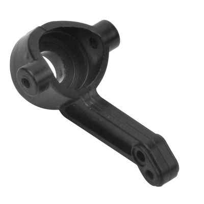
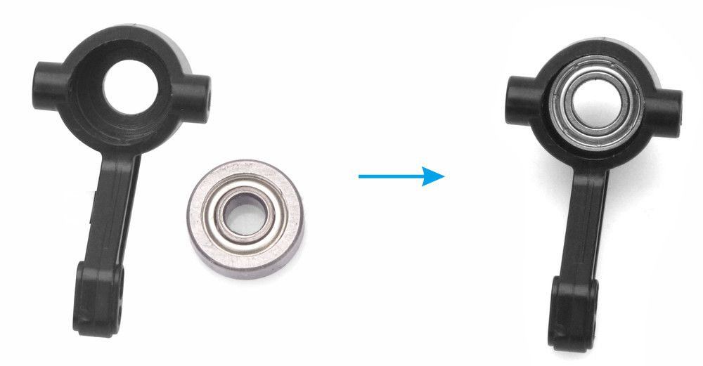
9. Push 4x12x4 roller bearing into front of RC steering cup tightly as follow:
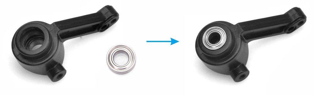
10. Push 4x8x4 roller bearing into back of RC steering cup tightly as follow:
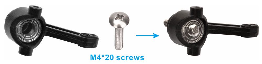
11. Use M4*20 screw cross RC steering cup as follow:
12. Fix Motor Flexible Couplers on M4*20 screw with Cup point screws as follow:
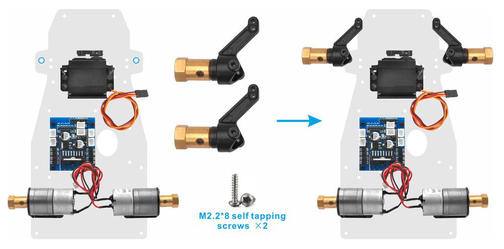
13. Fix RC steering cups on lower car chassis with M2.2*8 self-tapping screws as follow:
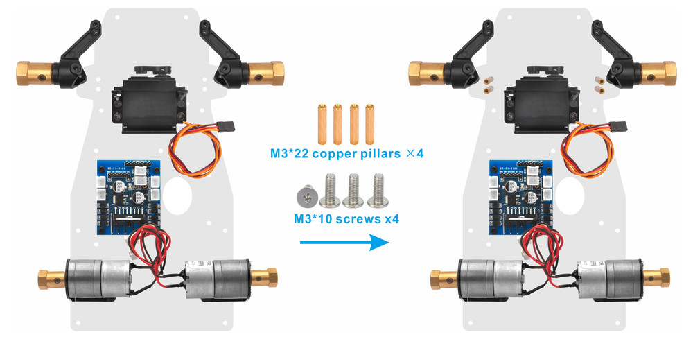
14. Install M3*22 copper pillars beside of RC steering cups with M3*10 screws as follow:
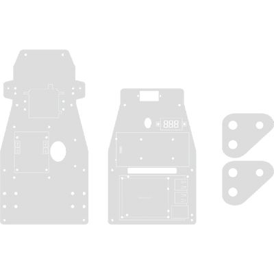
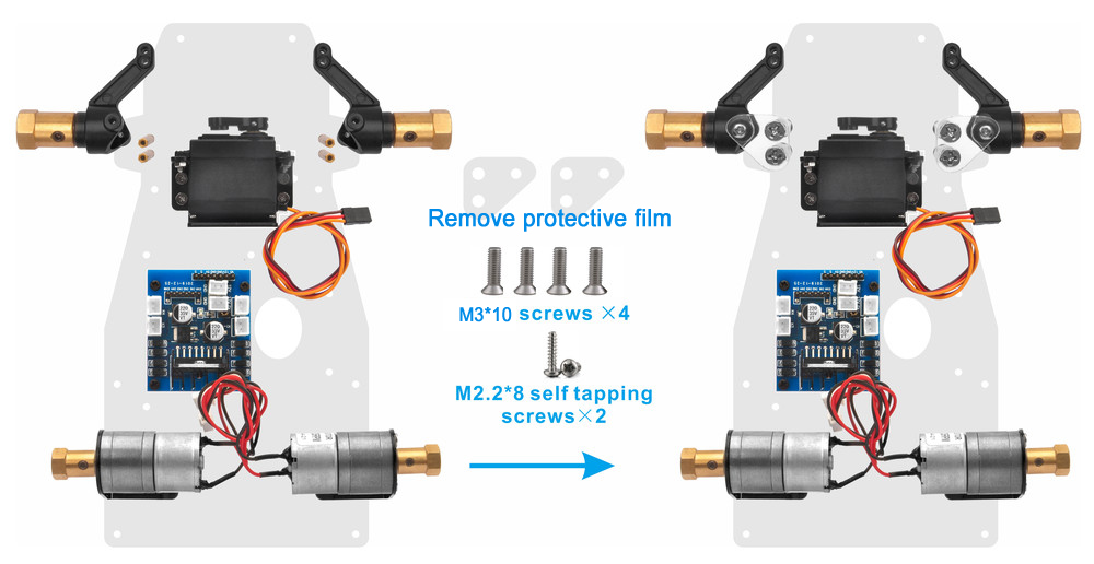
15. Install triangular Acrylic sheets on the M3*22 copper pillars and fix these with M2.2*8 self-tapping screws and M3*10 screws as follow:
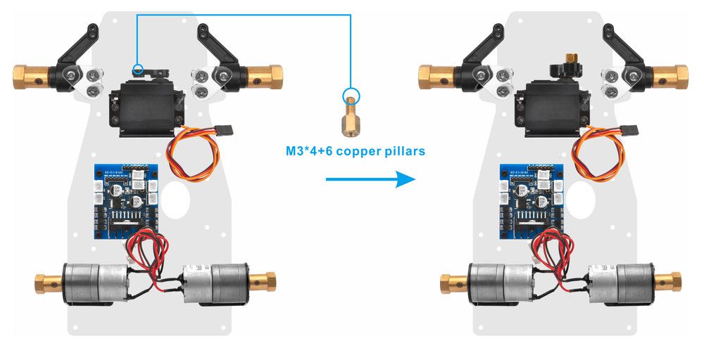
16. Install M3*4+6 copper pillar on servo horn as follow:
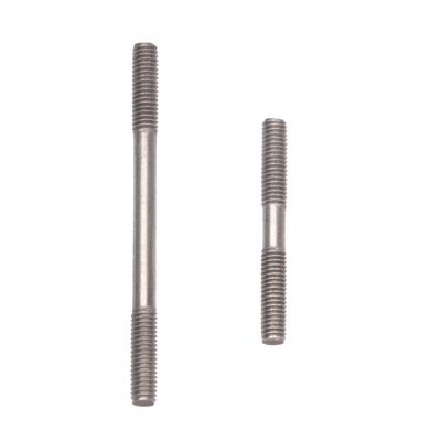
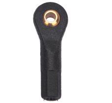
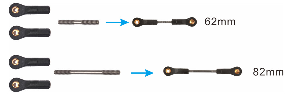
17. Fix 2 connecting rods with Rod radial end bearings, and make sure the lengths of these are about 62mm and 82mm
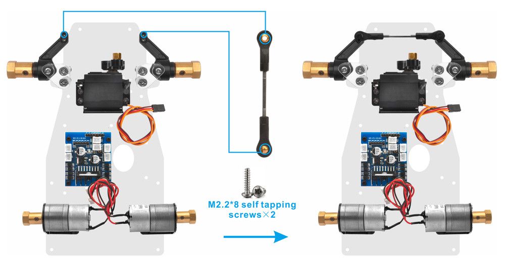
18. Install two ends of 82mm connecting rod under RC steering cups with 2pcs M2.2*8 self-tapping screws as follows (Note: When installing 82mm connecting rod, please keep the heads of two RC steering cups parallel, or you need to adjust the length of this connecting rod) :
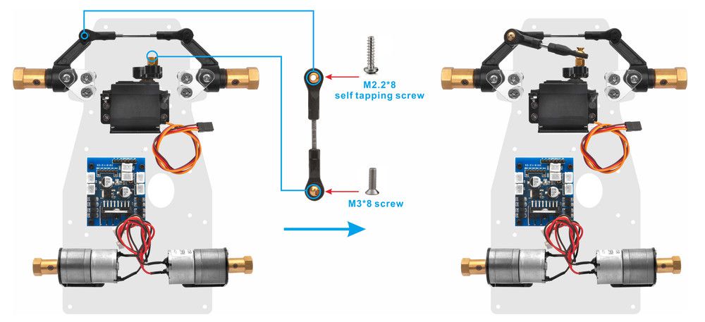
19. Install one end of 62mm connecting rod on left RC steering cup with M2.2*8 self-tapping screw and the other end on M3*4+6 copper pillar with M3*8 screw as follow( Note: When installing 62mm connecting rod, please keep the servo horn perpendicular to the micro servo, or you need to adjust the length of this connecting rod) :
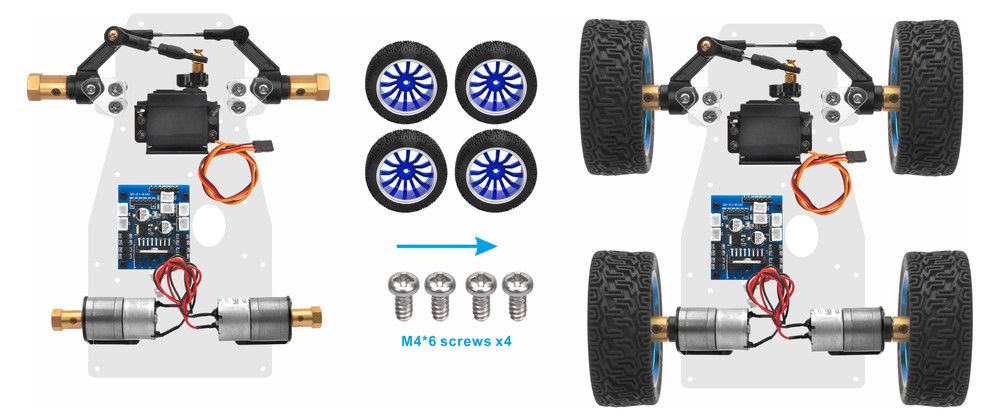
20. Install 4 wheels on motor flexible couplers with M4*6 screws as follow:
21. From bottom to top, use M3*8 cross M3 wash, lower chassis and M3*45 copper pillar to fix M3*45 copper pillar on low chassis as follow:
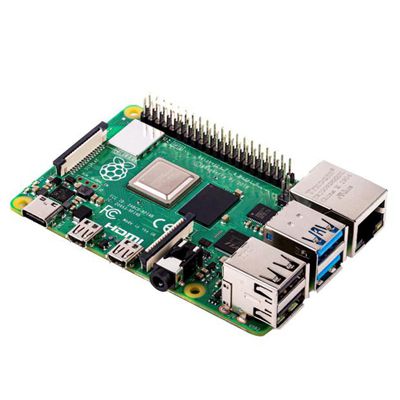
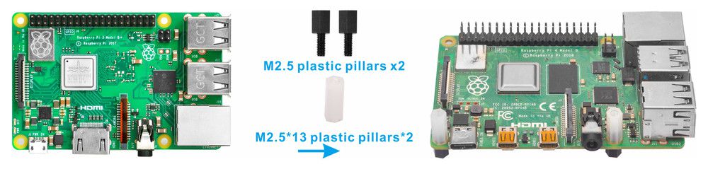
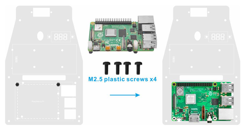
22. Use M2.5 plastic pillar cross Raspberry Pi and M2.5*13 plastic pillar from bottom to top and fix 2pcs M2.5*13 plastic pillars on Raspberry Pi as follow:
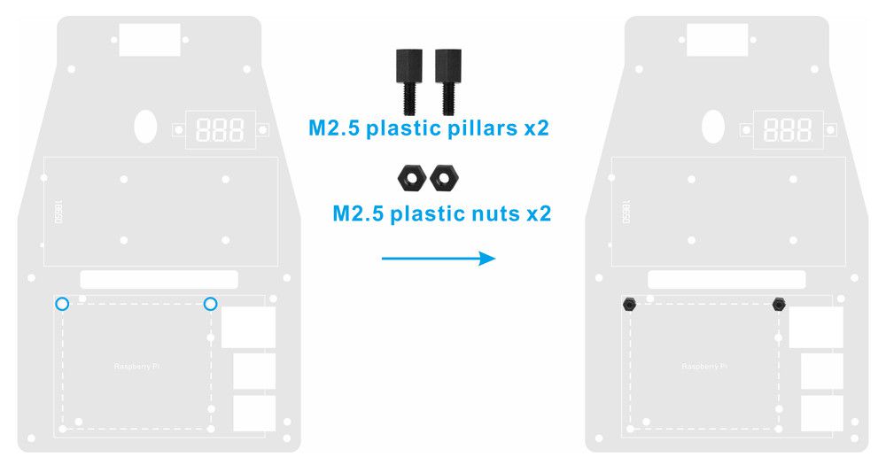
23. Fix 2pcs M2.5 plastic pillars on upper chassis as follow:
24. Install 2pcs M2.5 plastic screws under the chassis and 2pcs M2.5 plastic screws on Raspberry Pi
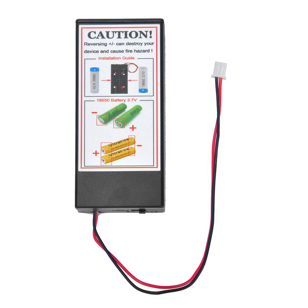
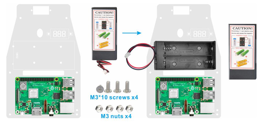
25. Fix 18650 battery box on upper chassis with M3*10 screws and M3 nuts
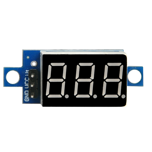
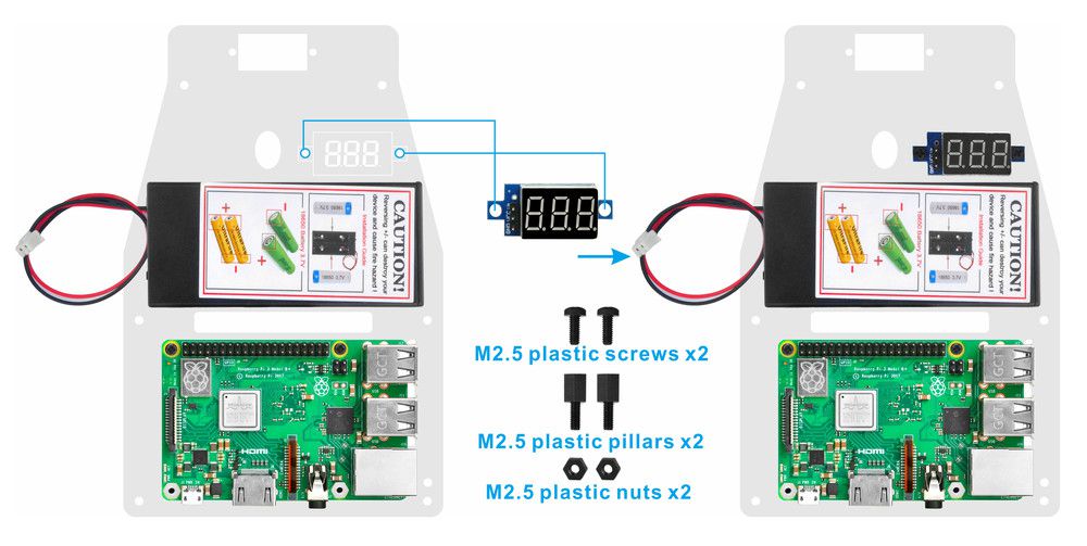
26. Install voltage meter on upper car chassis with 2pcs M2.5 plastic screws, plastic pillars and plastic nuts
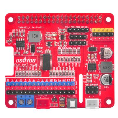
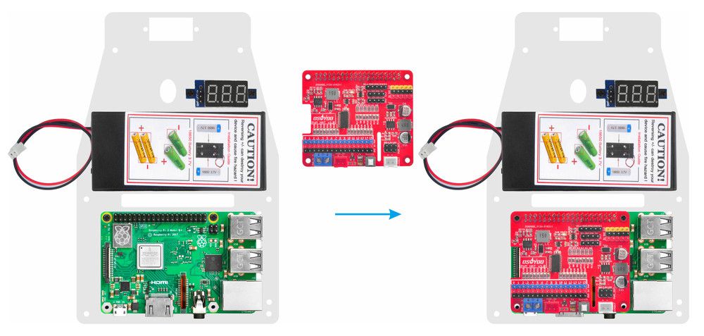
27. Insert OSOYOO PWM Hat V1.0 on Raspberry Pi as follow: Note: before fix upper chassis on lower chassis, please connect the parts. To learn more about the GPIO pins of Raspberry Pi, please visit: https://osoyoo.com/2017/06/26/introduction-of-raspberry-pi-gpio/
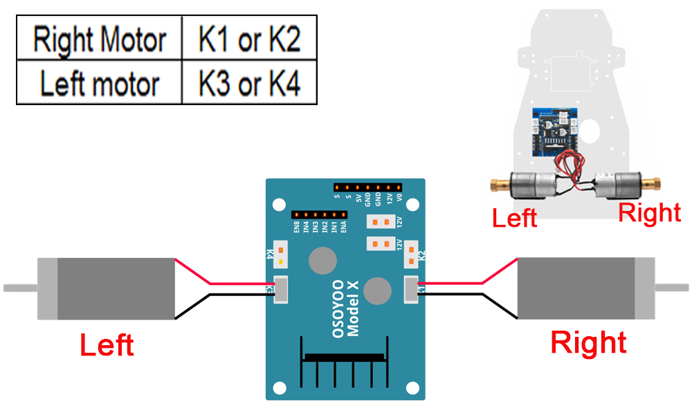
1) Connect left motor to OSOYOO MODEL X motor driver module K3 or K4 socket and right motor to K1 or K2 socket as following graph:
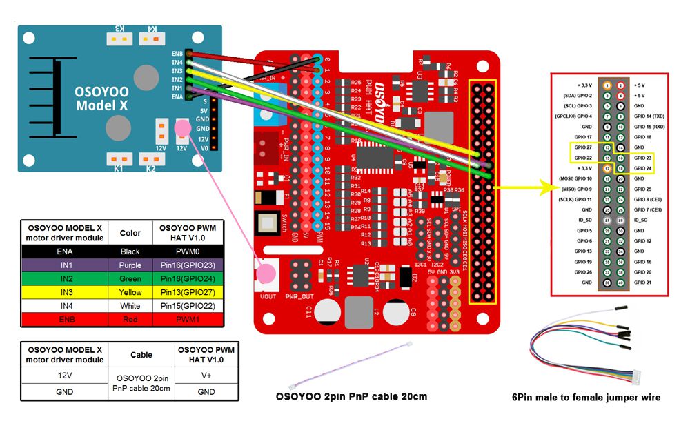
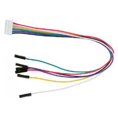
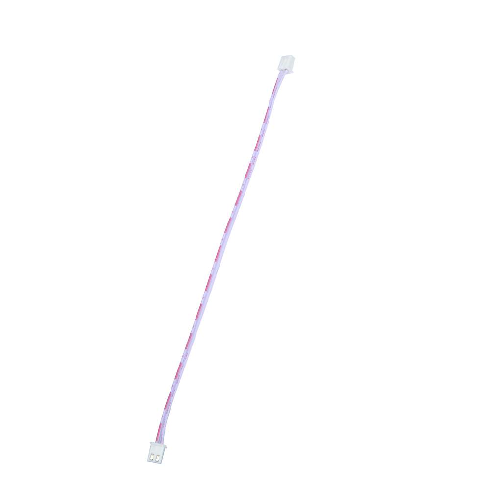
2) Connect OSOYOO MODEL X motor driver module to OSOYOO PWM Hat V1.0 with 6Pin female to female jumper wire, also connect 2pin 20cm cable as following graph
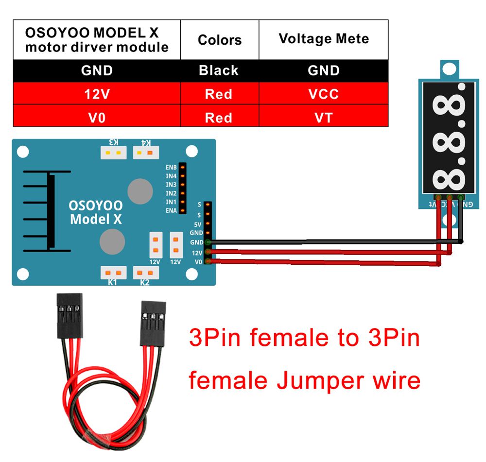
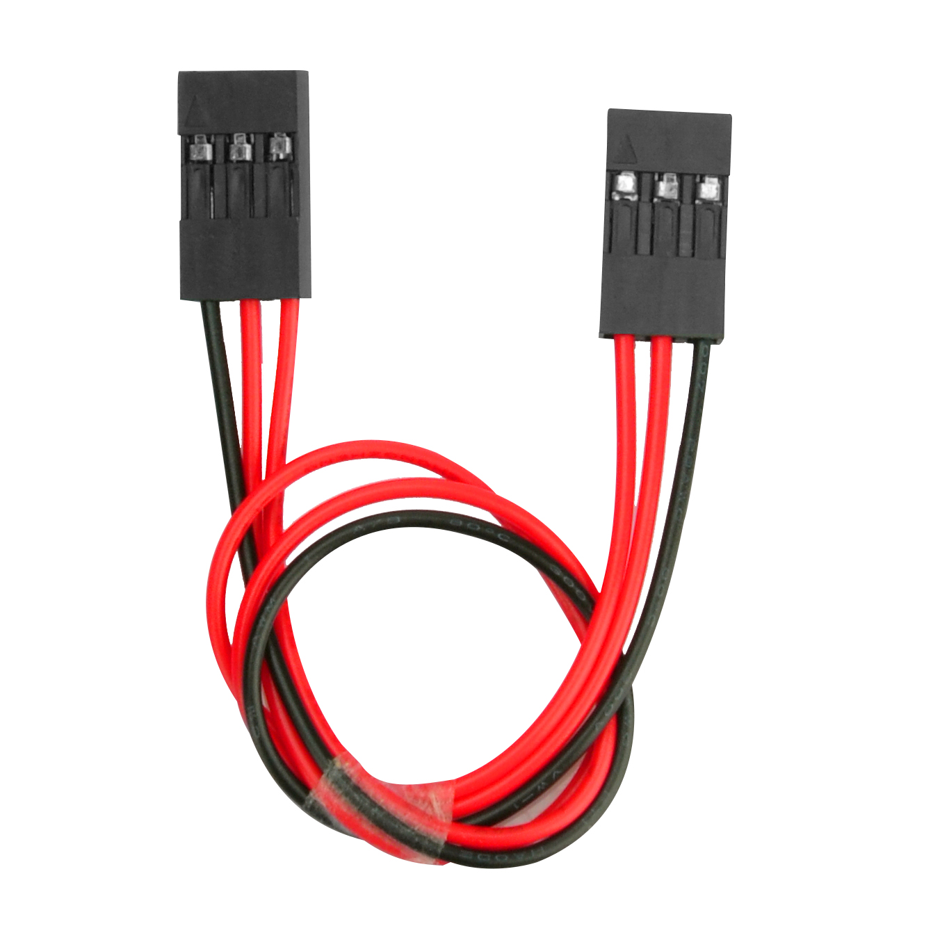
3) Connect Voltage Meter to OSOYOO MODEL X motor driver module with 3pin female to female jumper wires as below connection diagram
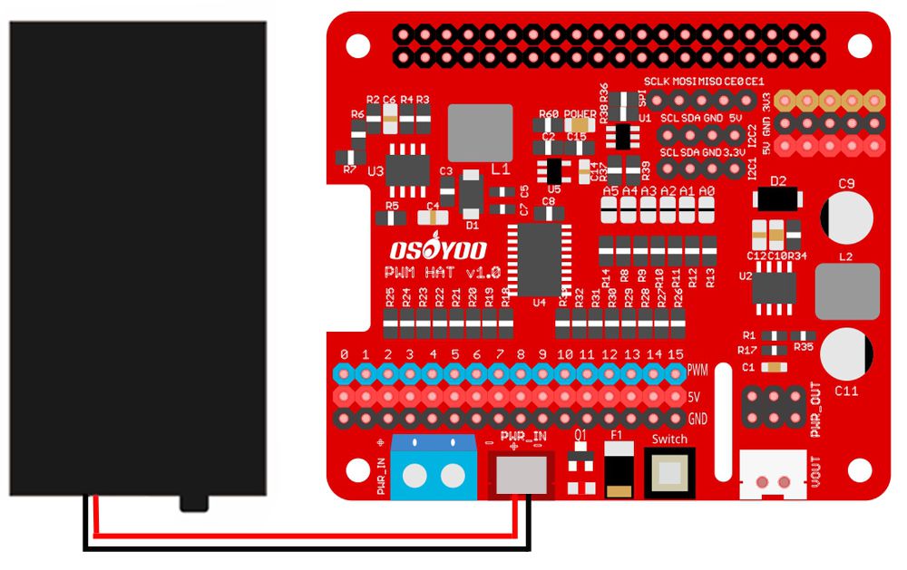
4) Connect 18650 battery box to OSOYOO PWM Hat V1.0 as below connection diagram
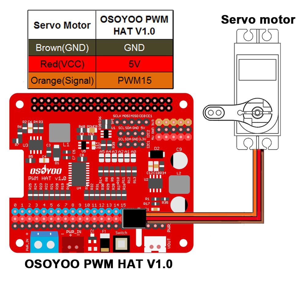
5) Connect Servo motor to 15 of OSOYOO PWM Hat V1.0 as following:
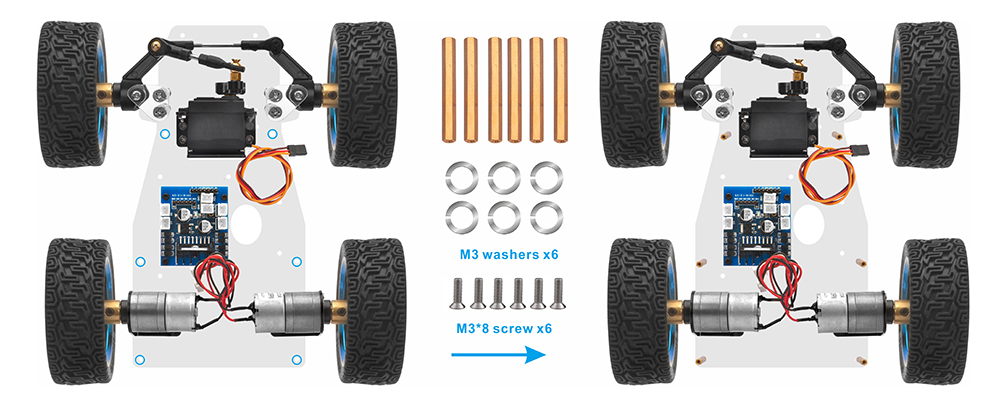
6) Connect upper chassis to lower chassis with 6 copper pillars and fix copper pillars with M3*8 screws and M3 washes as following:
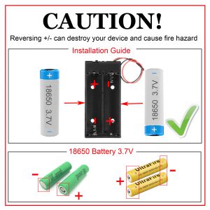
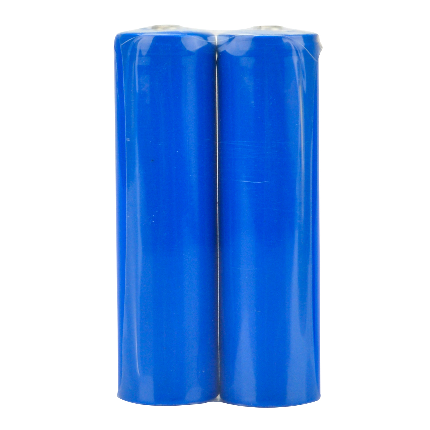
7) Please install your 18650 batteries in battery box for 18650 as per following instruction (Note:Check the box instruction and make sure polar direction is correct, otherwise it can destroy your device and cause fire hazard.):
Now hardware installation is almost down.


 Note: before fix upper chassis on lower chassis, please connect the parts. To learn more about the GPIO pins of Raspberry Pi, please visit: