Contents
| Buy from US |
Buy from UK |
Buy from DE |
Buy from IT |
Buy from FR |
Buy from ES |
Buy from JP |
|
|
|
|
|
|
 |
Overview
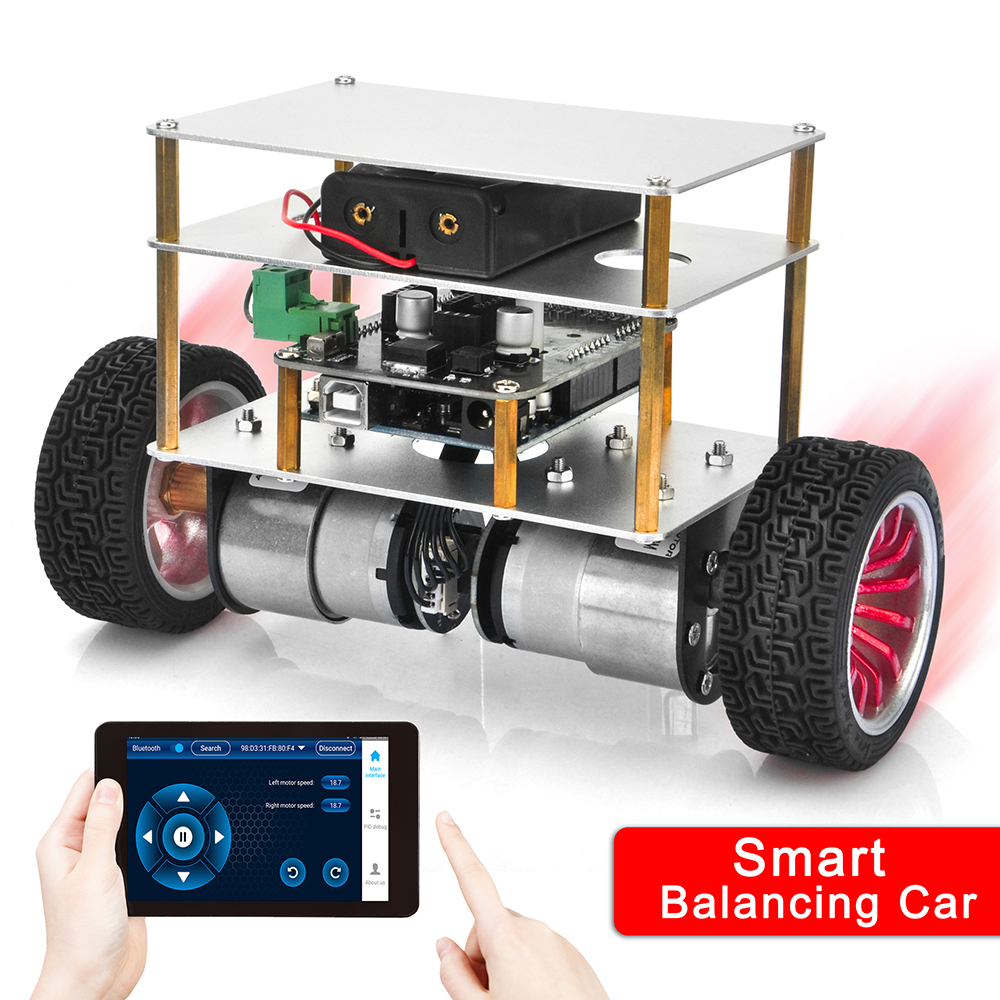
OSOYOO 2WD Balance Car Robot is a fun, educational kit which allows you to make, program, and control a two-wheeled, self-stabilizing motorized vehicle. Once constructed, the car will operate and attempt to maintain an upright position through controlled movements, or after encountering external forces, such as bumps or obstacles in its path. Users can control the car via Bluetooth using the free OSOYOO Balance Car app, available for Android.
It is a Arduino Based Self-balancing Robot Kit. The OSOYOO 2WD Balance Car Robot Car is Open Source and easy to assemble. It uses strong aluminium alloy structures and keeps the robot balanced using its center of gravity. In order to achieve high-performance, we tests various torque-gear motors to ensure the robot will keep balance and move flexibly even if it gets pushed suddenly.
Building the OSOYOO 2WD Balance Car Robot will be so much fun for novice and experienced robotics fans!

———————————————————————————————————–
Features
- Build a two-wheeled, self-balancing motorized vehicle.
- Wirelessly control the robot over Bluetooth using the free app for Android devices.
- Utilizes OSOYOO Series modules for enhancements and improvements.
- Customizable through the open-source Arduino architecture.
- Contains all required electronics and documentation.
- STEM education robot. In addition to being fun, this robot engage beginners and advanced students and incorporate many of the fundamental STEM concepts providing a learning platform that everyone enjoys
- Open Robot project: code and hardware design files are open and shared. You could personalise your robot as much as you want.
- DIY & Hackeable: OSOYOO 2WD Balance Car Robot is not a closed final product, it is an open, modifiable and hackeable platform, perfect to learn and play as much as you want!
- Develop your own apps: You could modify the source code of OSOYOO 2WD Balance Car RobotT to perform new tasks but the communication protocol is also open so you can develop your own IOS, Android, PC remote apps to control your ROBOT!
- Learn: This ROBOT is the OSOYOO product and this mean that you will receive a well documented project (source code and external documentation). We want you know all that is happening inside your Robot! This is ideal for learning and teaching technology. We will provide very good documentation. How we are controlling the motors, how we read and integrate the information from gyros and accelerometers, how we are controlling de stability of the robot, how we communicate with the control apps, etc…
– Build with your kids, at school, for yourself… this is a unique gadget. A perfect STEM education robot
– This self balancing robot has a medium size, perfect to carry your own beer (or mineral water ;-))
– There is a experienced technical support team behind OSOYOO so when you encounter problems, we will help you in the fastest way.
– You can use these self balancing robot parts to create more robots or gadgets, keep in mind all the devices used in a OSOYOO ROBOT are standard electronic devices with a lot of potential. You are now buying a self balancing robot, you are buying your a versatile set of electronics and ancillary devices.
Packing List
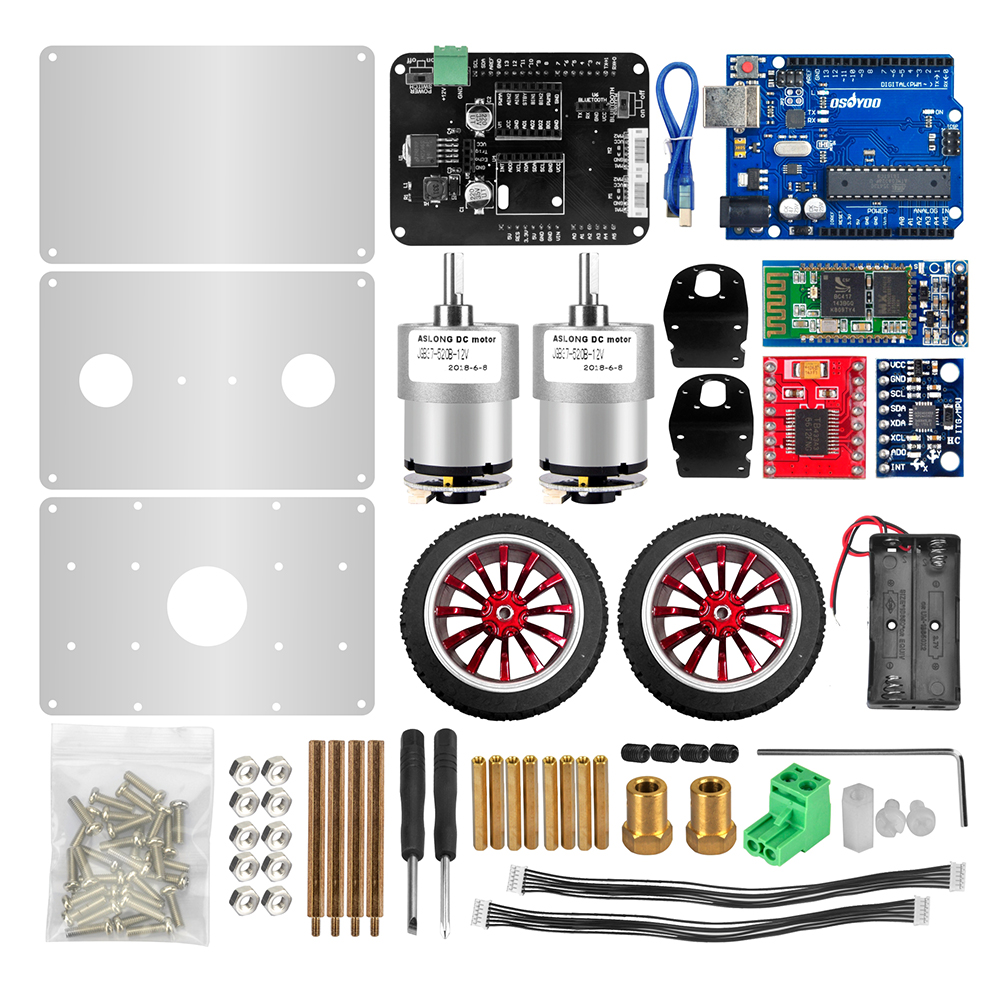
- OSOYOO UNO Board x 1
- OSOYOO Balance Robot Shield x 1
- HC-06 Bluetooth Module x 1
- MPU6050 Gyroscope module
- TB6612FNG Driver Module x 1
- GM37 Stepper Motor x 2
- Wheel x 2
- Screw, copper column, nut
- Aluminium alloy fixed plate x 3
- Battery box for 18650 batteries
- Terminal
- Stepper Motor Axis
- Motor bracke
- Single screwdriver
- Cross screwdriver
- Six angle wrench for no cap screw M3*4
- Jumper 6P*2
- Package x 1
Considering the safety of transportation, the 18650 battery is not included in the kit. (Click here to know how to get free18650 Rechargeable Li-ion battery from old laptop computer).
The OSOYOO 2WD Balance Car Robot is a two-wheeled self-balancing mobile robot kit. The kit is designed to be fun and easy to assemble. Meanwhile, learning about the different modules and their functions to create the robot.
Hardware Design
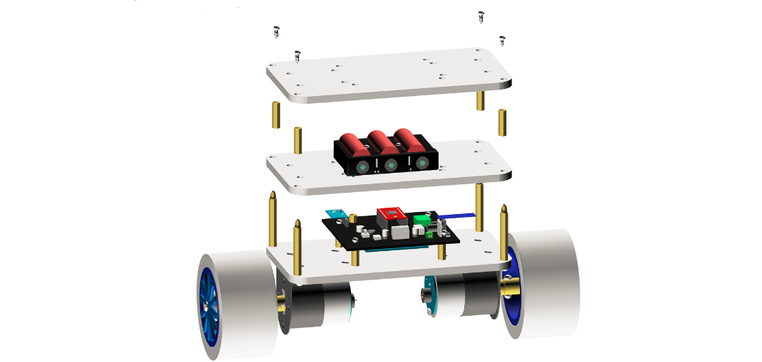
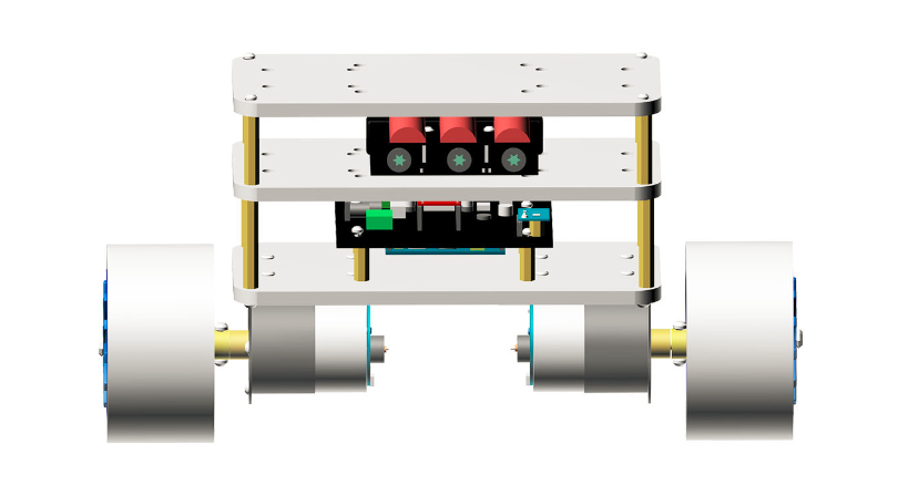
The OSOYOO 2WD Balance Car Robot kit includes everything you need to make your own self-balancing robot: two high torque and high speed gear motors, wheels, aluminium alloy structures, 18650 battery holder (batteries are not included), Balance Shield, and Arduino UNO-compatible board.
The OSOYOO 2WD Balance Car Robot uses three 1.5mm thick aluminium alloy boards and other accessories for its main structure. One board is used to fix the two motors. One of the boards is used to fix the battery and the other is for an Arduino-compatible board plus the Balance Shield.
Self-Balancing
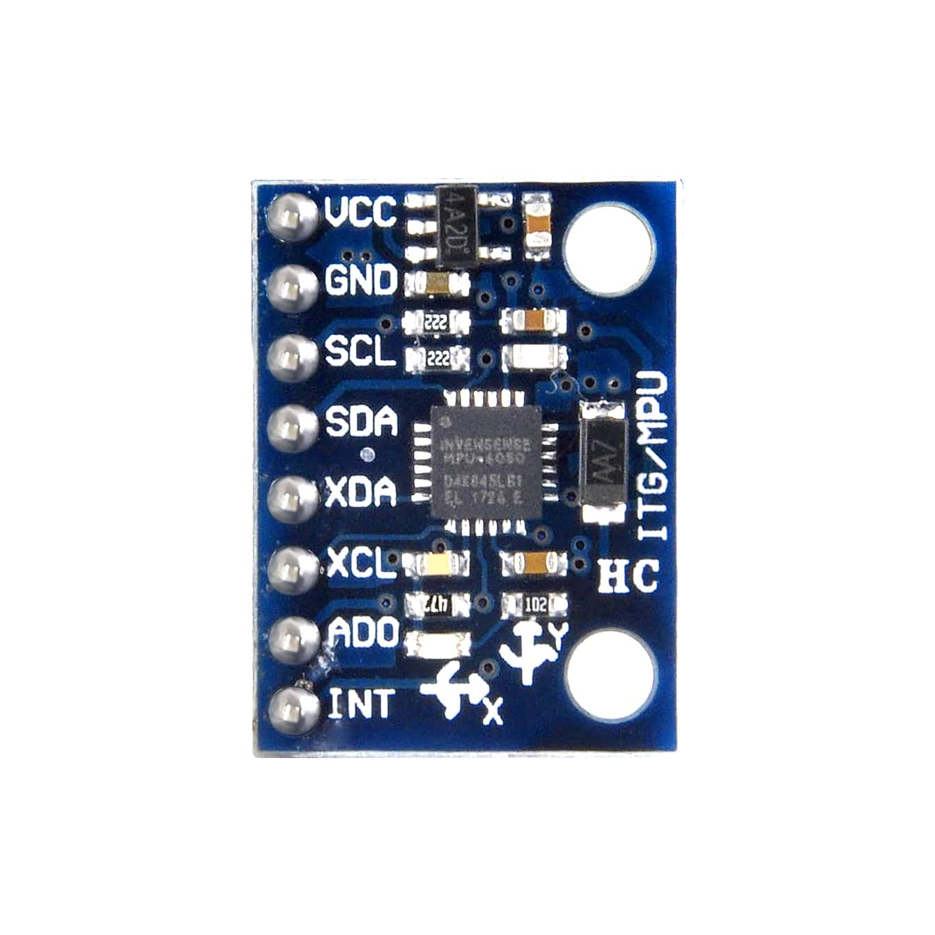
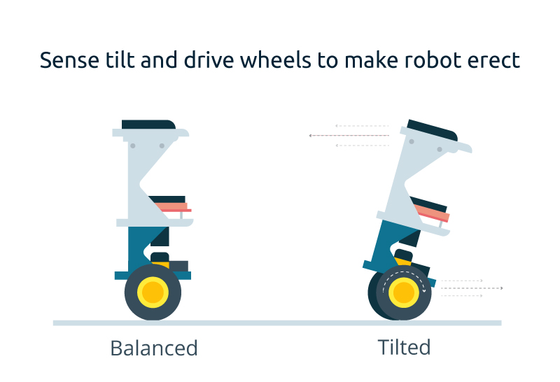
The robot utilizes a 3-axis accelerometer and a 3-axis gyroscope chip (MPU-6050) to determine if it is tilting over. Two stepper motors then activate appropriately to compensate for this falling motion to maintain the robot’s upright self-balancing position.
Wireless Control
The Bluetooth chip (included) adds wireless communication to the OSOYOO 2WD Balance Car Robot. The robot can be remotely controlled by mobile devices running Android app. Control from the app allows for forward, reverse and left / right steering all the while the robot continuously self-balances itself.
A Complete Kit
The kit contains everything needed to make the OSOYOO 2WD Balance Car Robot. Electronic hardware from the embedded processor (Core module) to the steppers motors and wheels are included. Also included are the precision laser cut enclosure pieces to house the eConsidering the safety of transportation, the 18650 battery is not included in the kit. (Click here to know how to get free18650 Rechargeable Li-ion battery from old laptop computer). lectronic hardware. The Open Source code is provided and can be modified for personal.
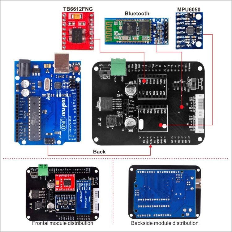
Electronic Components
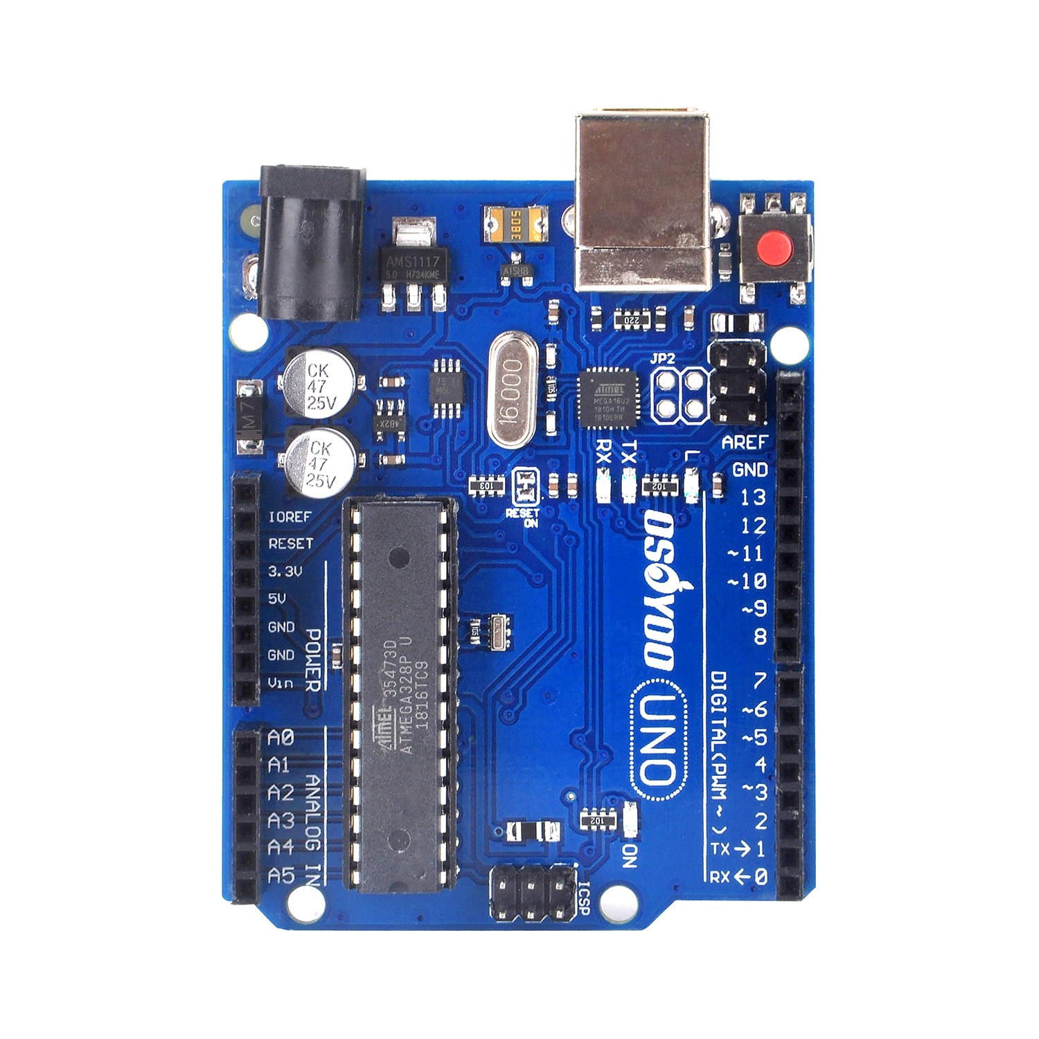
Arduino Compatible Board – OSOYOO UNO
The main controller chosen for the balancing robot is the Osoyoo UNO. It can be considered as the brain of the balancing robot and is connected to the IMU to process the tilt angle information. After processing, it will communicate with the motor driver in order to adjust the speed and direction of the motor.
Inertial measurement unit MPU-6050
The inertial measurement unit are electronic devices that measure and report about velocity, orientation and gravitational forces to which the device is subjected. IMUs combine information from various sensors, mainly magnetometers, accelerometers and gyroscopes. To use an IMU correctly, it will be necessary to combine the measurements of both devices. For this, two different methods are usually used:
- Complementary filter: based on the combination of a high pass and low pass filter. This filter main advantages are, easy implementation and low computational cost.
- Kalman filter: the algorithm was in 1960 by Rudolf E. Kalman. It allows to combine the information of different noisy sources minimizing the error through a predictive loop. Although better measures are obtained, the computational cost is much higher.
The aim of this process is to obtain a measure as realistic as possible of the navigation angles of the object. These angles are defined by solving the problem of determining the position and orientation of an object relative to a base in a three-dimensional space. Allow the relative orientation of both systems to be expressed by describing the orientation of an object by three orthogonal rotations about the X (roll), Y (pitch) and Z (yaw) axes. In our case, the MPU-6050 IMU was used, which incorporates a gyroscope and an accelerometer and is accessible using the I2C communication bus.
Gravity’s acceleration is used as reference to calculate the angle that the accelerometer will use. An accelerometer is not a suitable sensor to determine the speed of a system, much less its position. So another tool must be used to get the value of the inclination value:

A gyroscope is a device that allows us to measure the angle of rotations rotated by a certain mechanism. These devices, unlike the accelerometer, are purely differential devices, so that angles relative to an arbitrary reference are always measured. The main problem of gyroscopes comes from having to obtain the measurements through an integration, an accumulation of errors will occur in the measurement, causing a drift in the measurement, medium and long term, with respect to its real value.

The basic idea behind a complementary filter is to combine the two outputs obtained with the accelerometer and the gyroscope to obtain a good estimate of the orientation angle. The filter will behave as a low-pass filter for the measurement of the accelerometer, and as a high pass filter for the gyroscope measurement. In this way the high frequency components of the accelerometer are dominated by the gyroscope. The mathematical way to implement this filter is:

Where FC is a constant defined by the user which has usually a value between 0.85 and 0.95.
Bluetooth module HC-06
Because we want to be able to control the robot using a smartphone, the easiest solution found was to use a bluetooth wireless communication module. The chosen device is a bluetooth module HC-06, which can be controlled using a communication via serial port.
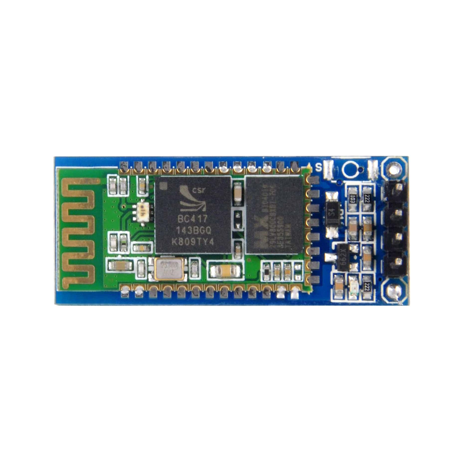
More info about HC-06 please check this link: https://osoyoo.com/2017/10/25/arduino-lesson-hc-06-bluetooth-module/
DC motors with encoders
In order to grant movement to the robot it will be necessary to use motors. From all of the engines available (brushless, stepper…) we chose DC engines because they have good torque and speed control.
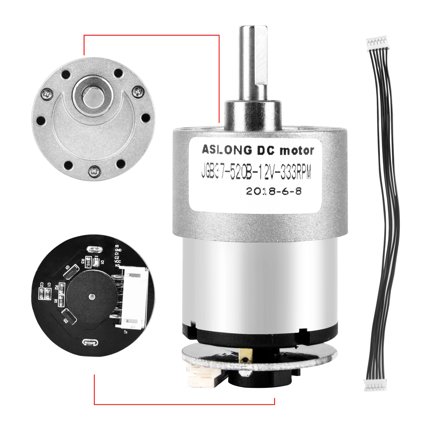
For the DC motor used, below are the features of the DC motor:
i. Rated speed is 130rpm. The robot requires an average rpm so that it could counter the balancing error in a suitable speed. Low speed might not be able to balance the robot properly. Therefore, a higher rpm is chosen.
ii. Rated torque is 127.4 mN.m. The torque of the motors must be carefully chosen because a low torque might not be capable to balance the robot. The torque does not necessarily be too high. The torque required is based on the formula, Torque = Force x Distance
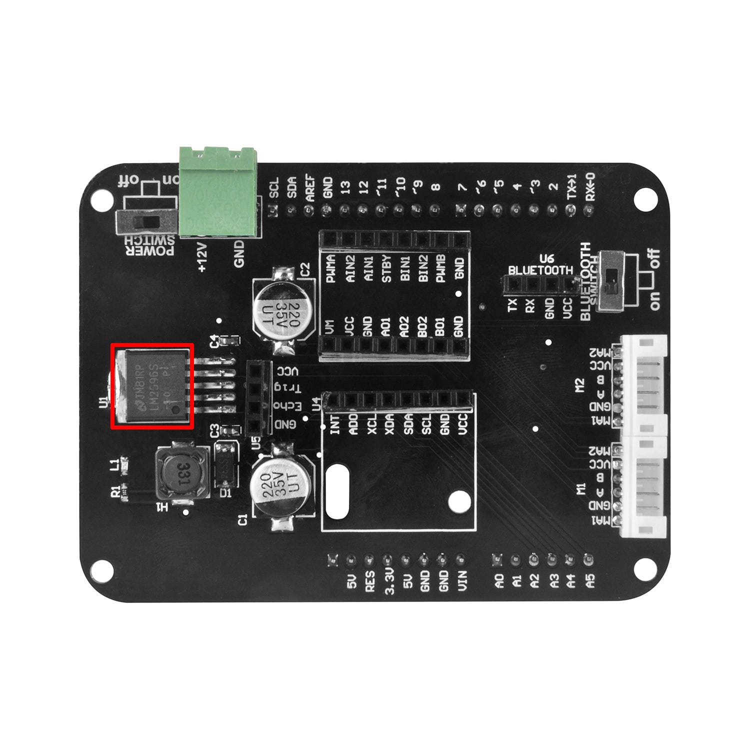
Voltage regulator LM2596S
The LM2596 series of regulators are monolithic integrated circuits that provide all the active functions for a step-down (buck) switching regulator, capable of driving a 3-A load with excellent line and load regulation. These devices are available in fixed output voltages of 3.3 V, 5 V, 12 V, and an adjustable output version.
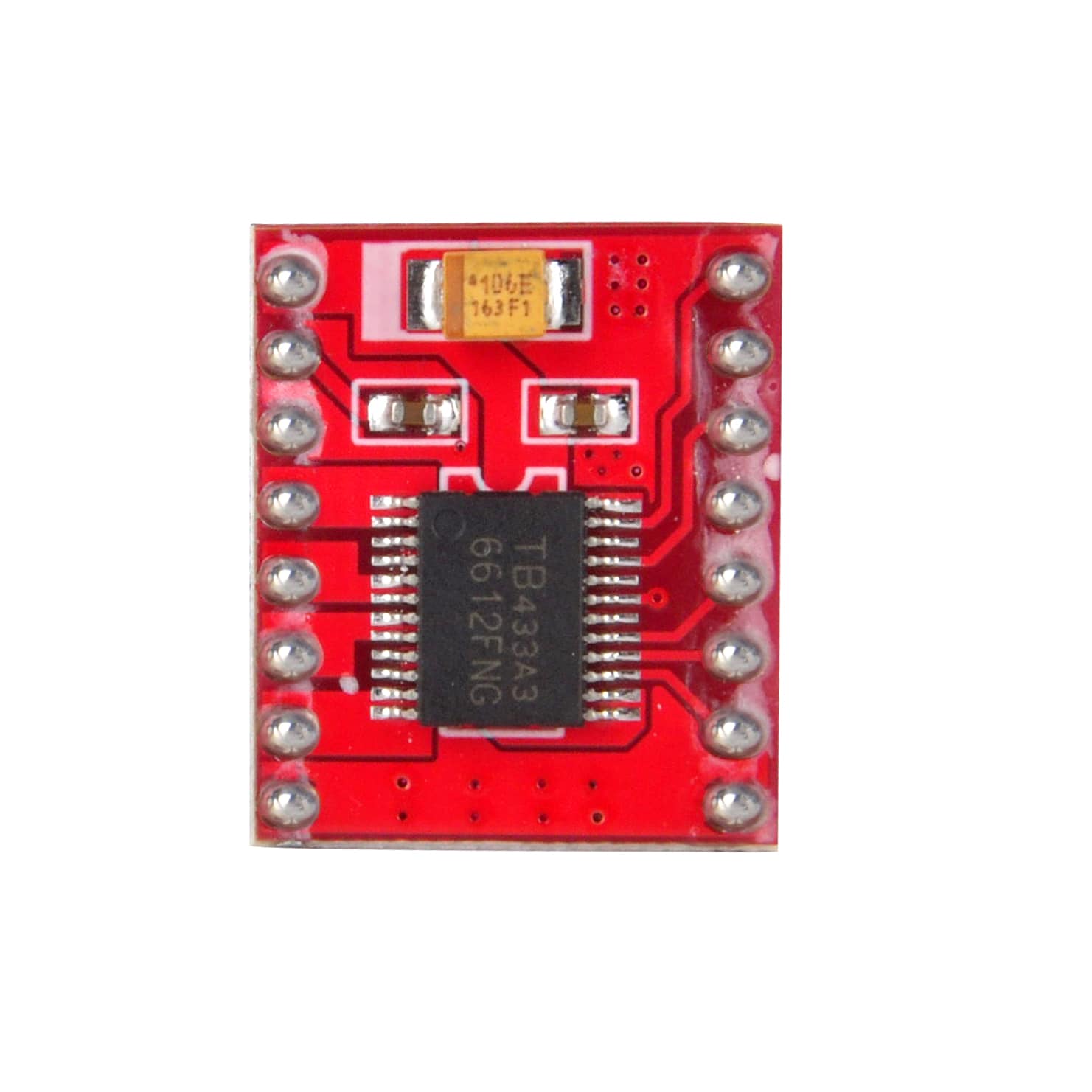
Driver TB6612FNG
The TB6612FNG Motor Driver can control up to two DC motors at a constant current of 1.2A (3.2A peak). Two input signals (IN1 and IN2) can be used to control the motor in one of four function modes: CW, CCW, short-brake, and stop. The two motor outputs (A and B) can be separately controlled, and the speed of each motor is controlled via a PWM input signal with a frequency up to 100kHz. The STBY pin should be pulled high to take the motor out of standby mode.
Expanding Reading
If you are not so familiar with the Arduino, you’d better go through the following tutorials before you start exploring this new product:
Connection
Though the OSOYOO 2WD Balance Car Robot will be assembled to retransport, here we will demonstrate how to assemble it for those who need deep development.
Main controller board connection
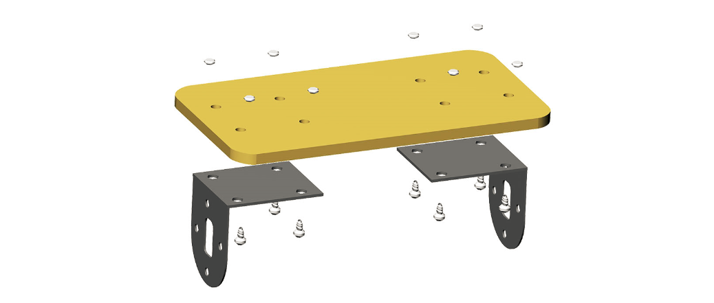
Installation of motor fixed bracket
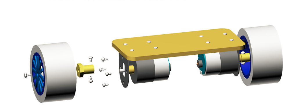
Installation of motor, shaft connector and tire
Installation of OSOYOO Balance Robot main controller

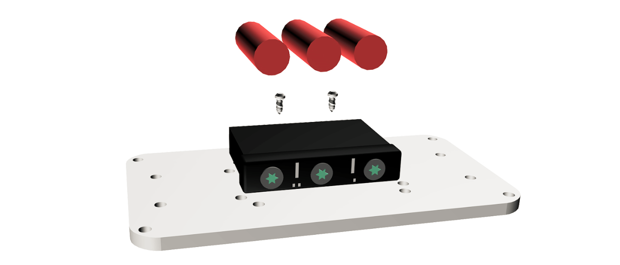
Battery box installation
Robot Frame installation
How does it work?
OSOYOO 2WD Balance Car Robot is a remotely controlledself balancing Arduino robot created with aluminium alloy parts. With only two wheels, it is able to maintain its balance all the time by using his internal sensors and driving the motors. You can control your Robot, making him move or spin, by sending commands via a Smartphone, Tablet while it maintains its balance.
To keep the robot balanced, the motors must counteract the robot falling. This action requires feedback and correcting elements. The feedback element is the MPU6050 gyroscope + accelerometer, which gives both acceleration and rotation in all three axes (MPU6050 I2C basics). The Arduino uses this to know the current orientation of the robot. The correcting element is the motor and wheel combination.
>More Self-balancing Theories
In control theory, keeping some variable (in this case, the position of the robot) steady needs a special controller called a PID (proportional integral derivative). Each of these parameters has “gains”, normally called Kp, Ki, and Kd. PID provides correction between the desired value (or input) and the actual value (or output). The difference between the input and the output is called “error”. The PID controller reduces the error to the smallest value possible by continually adjusting the output. In our Arduino self-balancing robot, the input (which is the desired tilt, in degrees) is set by software. The MPU6050 reads the current tilt of the robot and feeds it to the PID algorithm, which performs calculations to control the motor and keep the robot in the upright position. PID requires that the gains Kp, Ki, and Kd values be “tuned” to optimal values. Engineers use software like MATLAB to compute these values automatically. Unfortunately, we can’t use MATLAB in our case because it would further complicate the project. We will tune the PID values manually instead. Here’s how to do this:
-
- Make Kp, Ki, and Kd equal to zero.
- Adjust Kp. Too little Kp will make the robot fall over, because there’s not enough correction. Too much Kp will make the robot go back and forth wildly. A good enough Kp will make the robot go slightly back and forth (or oscillate a little).
- Once the Kp is set, adjust Kd. A good Kd value will lessen the oscillations until the robot is almost steady. Also, the right amount of Kd will keep the robot standing, even if pushed.
- Lastly, set the Ki. The robot will oscillate when turned on, even if the Kp and Kd are set, but will stabilize in time. The correct Ki value will shorten the time it takes for the robot to stabilize.
A bit more in depth…
The physical problem that B-ROBOT solves is called the Inverted Pendulum. This is the same mechanism you need to balance an umbrella above your hand. The pivot point is under the center of mass of the object. More information on Inverted Pendulum here. The mathematical solution to the problem is not easy but we don’t need to understand it in order to solve our robot´s balance issue. What we need to know is how should do to restore the robot´s balance so we can implement a Control Algorithm to resolve the problem.
A Control System is very useful in Robotics (an Industrial automation). Basically it´s a code that receives information from sensors and target commands as inputs and creates, in consequence, output signals to drive the Robot actuators (the motors in our example) in order to regulate the system. We are using a PID controller (Proportional + Derivative + Integral). This type of control has 3 constants to adjust kP,kD,kI.
From Wikipedia: “A PID controller calculates an ‘error’ value as the difference between a measured [Input] and a desired setpoint. The controller attempts to minimize the error by adjusting [an Output].”
So, you tell the PID what to measure (the “Input”) ,where you want that measurement to be (the “Setpoint”,) and the variable you wish to adjust to make that happen (the “Output”.) The PID then adjusts the output trying to make the input equal the setpoint.
For reference, a water tank we want to fill up to a level, the Input, Setpoint, and Output would be the level according to the water level sensor, the desired water level and the water pumped into the tank.
kP is the Proportional part and is the main part of the control, this part is proportional to the error. kD is the Derivative part and is applied to the derivative of the error. This part depends on the dynamics of the system (depends on the robot,´s weight motors, inertias…). The last one, kI is applied to the integral of the error and is used to reduce steady errors, it is like a trim on the final output (think in the trim buttons on an RC car steering wheel to make the car go totally straight, kI removes the offset between the target required and the actual value).
More information on PID controller here.
On OSOYOO ROBOT the steering command from the user is added to the motors output (one motor with a positive sign and the other with a negative sign). For example if the user sends the steering command 6 to turn to the right (from -10 to 10) we need to add 6 to the left motor value and subtract 6 from the right motor. If the robot is not moving forward or backwards, the result of the steering command is a spin of the robot.

Above: Top view of the Robot and the commands to the motors
You can click here to get more info about the PID control of the self-balacing robot.
Code Program
We pre-installed the program for each robot before it was shipped. The code and design files are open and shared. You could personalise your robot as much as you want. OSOYOO 2WD Balance Car Robot is not a closed final product, it is an open, modifiable and hackeable platform, perfect to learn and play as much as you want!
Note: Before upload the code to your Arduino board, please install the libraries first, since our compressed file contains multiple library files, you need to download it as a ZIP file, expand it and put in the proper directory.
Arduino Libraries for the Balance Kit
Download the Code here
For geeks who are very practical, you could modify the source code of this robot to perform new tasks but the communication protocol is also open so you can develop your own IOS, Android, PC remote apps to control your OSOYOO 2WD Balance Car Robot!
Note: When uploading the program, the bluetooth switch beside the bluetooth of the balancing car needs to be put to “OFF”, because the uploading program uses serial communication, occupying the digital port 0 (RX), 1 (TX), so when uploading the program can not be followed by Bluetooth module. Put the bluetooth switch to “ON” after the program is uploaded.
What about the user control?
NEW: (Android devices) control your OSOYOO 2WD Balance Car Robot using the Balance Car APP!
We have developed an APP for Android users that simplifies the control of the OSOYOO 2WD Balance Car Robot, so you can adjust the stability and behaviour of the OSOYOO 2WD Balance Car Robot in real time.
Also you can search “OSOYOO BALANCE Arduino ROBOT CAR” in GOOGLE PLAY to install it.
Click here to get more info about how to use the Android APP to control the OSOYOO self-balance robot.
iOS SOFTWARE
We are looking for some one who will be intrested in developing iOS app for Balanbot.
You know we can use a Bluetooth 4.0 Low Energe (BLE) module to connect Balanbot with iOS device (iPhone 4S and above). We will share the protocol and Android code to you, and help you understand the communication method we use. Now you need is just coding for iOS and share it to all the fans later.
What is really important is, we must be open for everyone. Open the hardware and open the software.
When you have done iOS, then tell us and we will share people where the App is.
FAQs and Notes
Notes and FAQs for the OSOYOO 2WD Balance Car Robot
Reference


