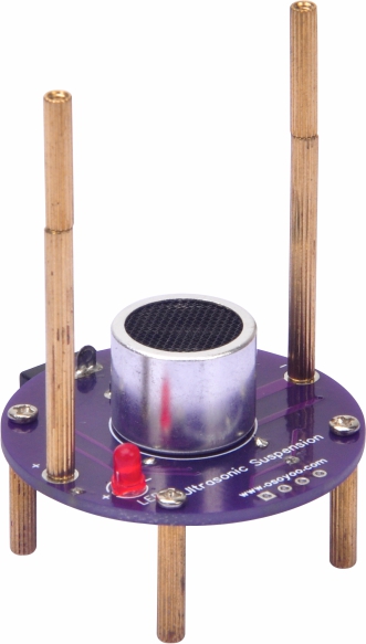
This is the OSOYOO Ultrasonic Levitation DIY Kit — a hands-on soldering practice project.
It will help you practice soldering skills, become familiar with a variety of electronic components, and deliver a dynamic result. When the circuit is assembled and soldered correctly, the LED will light up and four balls will levitate.
2. Working Principle:
Ultrasonic standing-wave levitation works by maintaining a precise gap between the ultrasonic transmitter and the reflector (or a second transmitter). This gap — called the resonant cavity distance — causes the transmitted and reflected waves to overlap continuously and form a standing wave. The acoustic-radiation force at the standing-wave nodes overcomes gravity and keeps objects suspended in mid-air.
1> Only light, small objects can be suspended — heavier objects cannot levitate.
2>. The ultrasonic transducers are sensitive to vibration. Avoid dropping or bumping them. After soldering the transducers, do not cut off any excess metal pins.
3>. Because the levitated objects are very light, air currents can disturb them. Place the assembled kit in a calm, draft-free location.
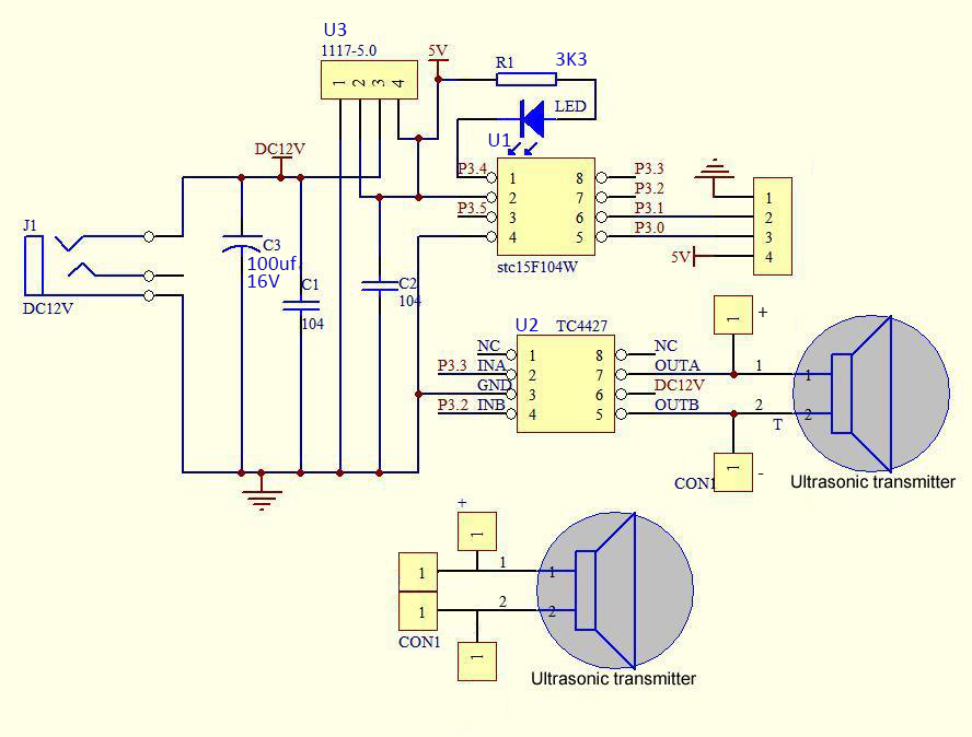
5. Schematic Diagram:
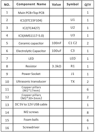
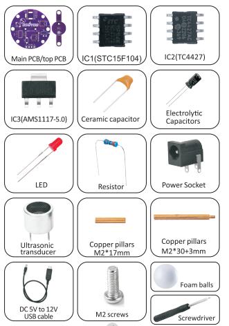
6. Component List:
PCB ASSEMBLY:
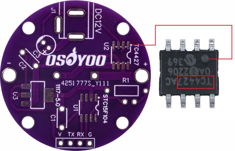
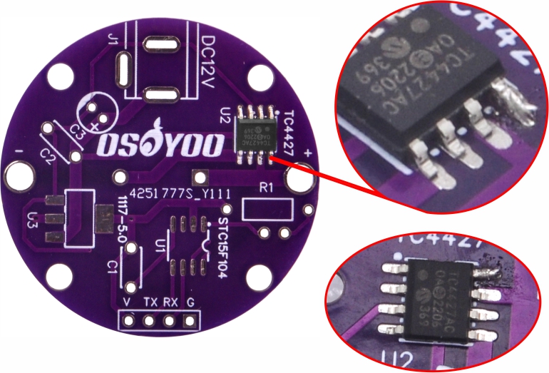
Step 1: Mount TC IC (TC4427) on U2.
1.1) Make sure the notch on the IC faces the same direction as the marking on the PCB. (Note: Pay close attention to IC orientation.)
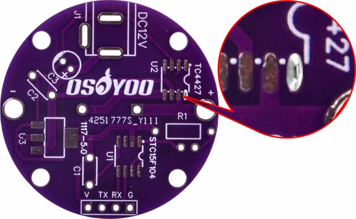
1.2) Select a solder pad on the PCB, then apply solder to the pads.
1.3) Use tweezers to position the IC (TC4427) on the pads and hold it in place. Touch the soldering iron to one leg to melt the solder and tack the IC down. 1.4) Solder the remaining legs of the IC (TC4427).
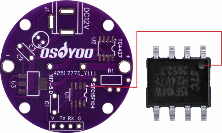
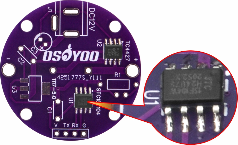
Step 2: Mount STC IC (STC15F) on U1 using the same method.
Make sure the dot on the IC faces the same direction as the marking on the PCB.
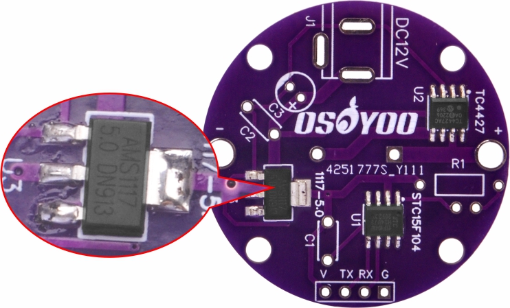
Step 3: Mount IC (AMS1117) on U3 using the same method.
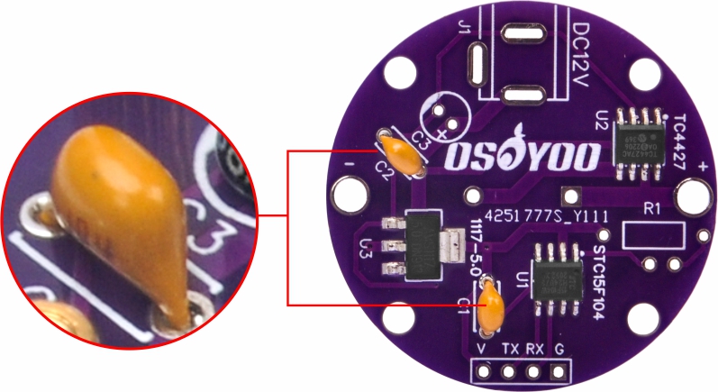
Step 4: Mount two 100 nF ceramic capacitors on C1 and C2.
Solder and trim the excess leads.
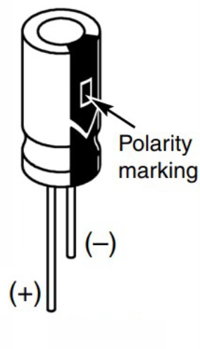
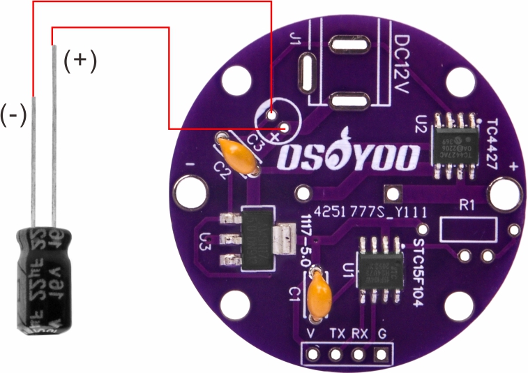
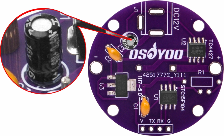
Step 5: Mount a 100 µF electrolytic capacitor on C3.
(Note: Electrolytic capacitors are polarized. Be sure to insert the positive (+) lead into the hole marked (+) on the PCB.)
Warning: Connecting the capacitor with incorrect polarity can cause it to heat up, leak, or explode.
Solder and trim the excess leads.
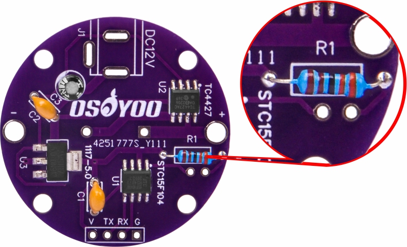
Step 6: Mount a resistor on R1.
Solder and trim the excess leads.
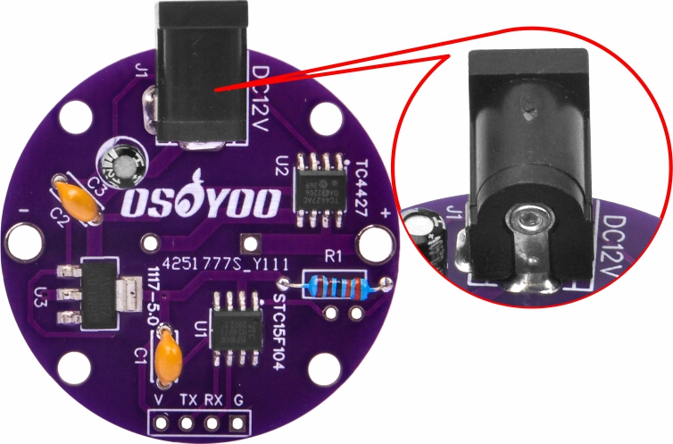
Step 7: Mount the power socket on J1 and solder.
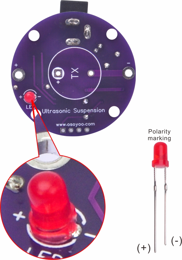
Step 8: Mount a red LED on the other side of the PCB.
(Note: LEDs are polarized. Be sure to insert the positive (+) lead into the hole marked (+) on the PCB.)
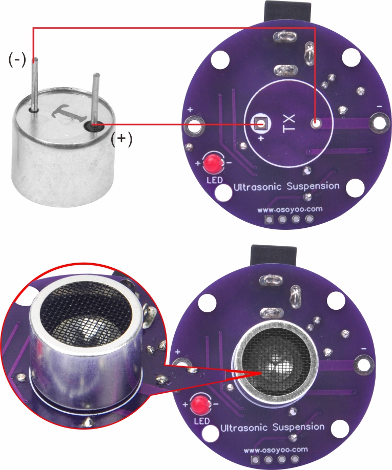
Solder and trim the excess leads. Step 9: Mount an ultrasonic transducer on the main PCB.
Note: The ultrasonic transducer has two pins. The pin with a black circle around it is the positive (+) leg — insert it into the hole marked (+) on the PCB.
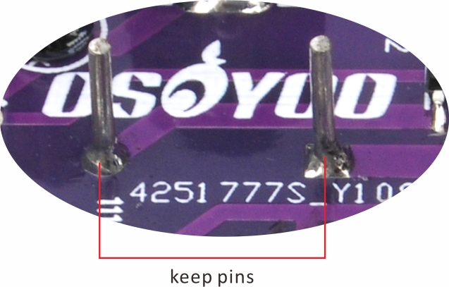
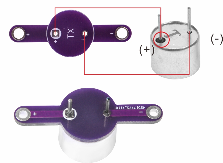
Solder and keep the metal pins. Step 10: Mount the second ultrasonic transducer on the top PCB.
Solder and keep the metal pins.
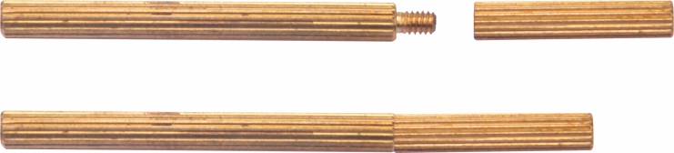
Step 11: Secure M2×17mm copper pillars to the main PCB using M2 screws.
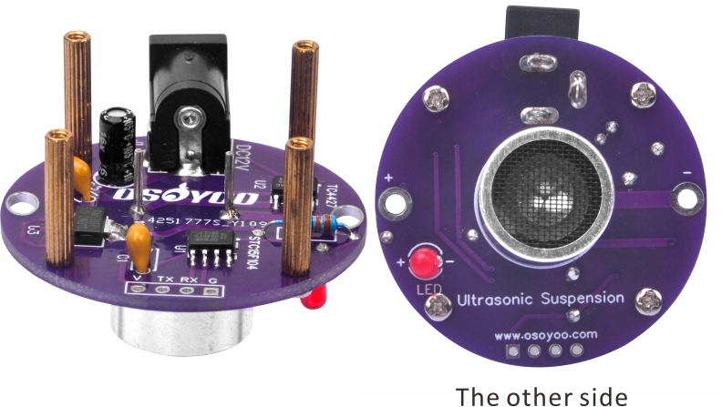
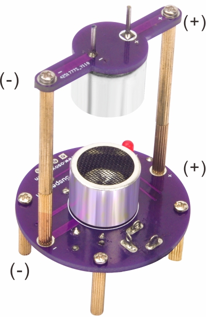
Step 12: Connect the M2×17mm copper pillar to the M2×30+3mm copper pillar screw to form a single copper standoff. Step 13: Secure the top PCB to the main PCB using the 2 copper standoffs from the previous step and 4 M2 screws.
(Make sure the positive electrodes of both PCBs face each other.)
Step 14: Operation
After completing assembly, review all solder joints and verify that every component is seated correctly. If everything looks good, connect the USB cable — the LED will light up. Use tweezers to position the included foam balls in the levitation zone.
Enjoy the science — make the foam balls float!
Note: The included USB cable boosts 5V to 12V and can be connected directly to a computer USB port to power the kit.
Safety Precautions:
Like all electrical devices, this kit must be handled with care. The soldering iron tip can reach high temperatures — please follow these safety rules:
⊙ Keep this kit out of reach of children.
⊙ Keep flammable materials away from the soldering iron.
⊙ Do not cool the iron by dipping it in any liquid or water.
⊙ Work in a well-ventilated area.


 1.4) Solder the remaining legs of the IC (TC4427).
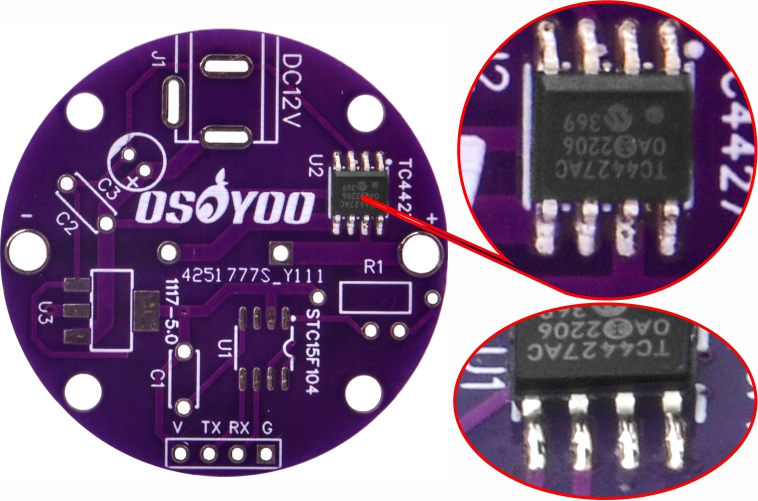
 Step 9: Mount an ultrasonic transducer on the main PCB.