Model 2021006600
The Mecanum omni-directional wheel is a fascinating type of wheel that allows a robot car to move in any direction — including parallel shifts to the left and right.
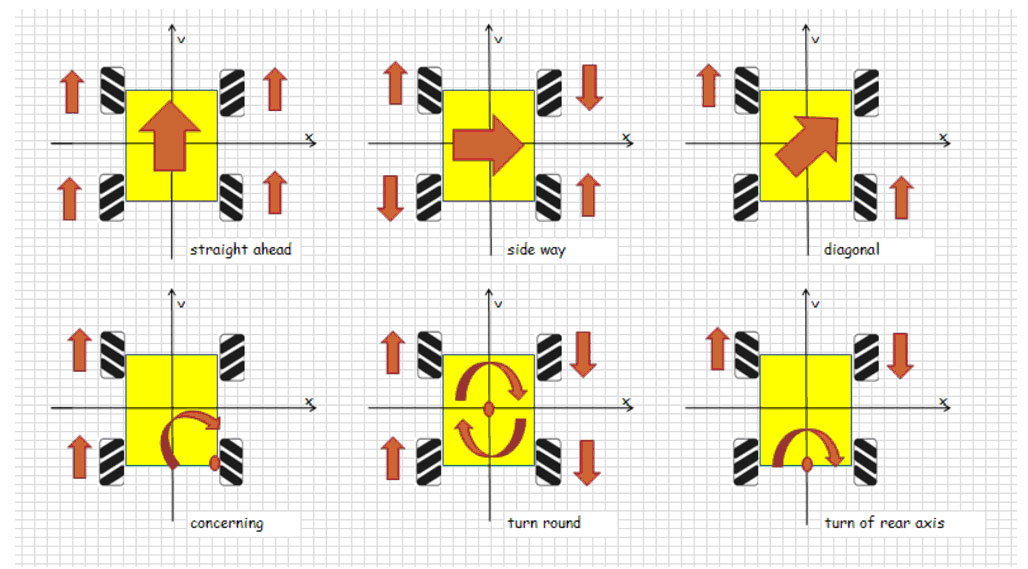
In this project, we will show you how to use a Raspberry Pi to control an OSOYOO Mecanum wheel robot car to perform basic movements: forward, backward, left turn, right turn, parallel left shift, and parallel right shift.
This lesson also guides you through assembling the car chassis and connecting the Raspberry Pi and OSOYOO PWM HAT to the OSOYOO Model Y board. This setup serves as the foundation for all following lessons.
OSOYOO Mecanum wheels robotic car chassis x1
OSOYOO Wheels and motors x4 (left wheels x2 / right wheels x2)
Raspberry Pi 4/5 board x1 (not included in this kit)
OSOYOO PWM HAT shield x1
OSOYOO Model Y motor driver board x1
OSOYOO Voltage meter x1
OSOYOO Battery box x1
OSOYOO 6-pin female-to-female jumper wire x2
OSOYOO 3-pin female-to-female jumper wire x1
OSOYOO 2-pin XH2.54 PnP female-to-female cable x1
18650 Batteries (3.7V) x2
Battery charger x1
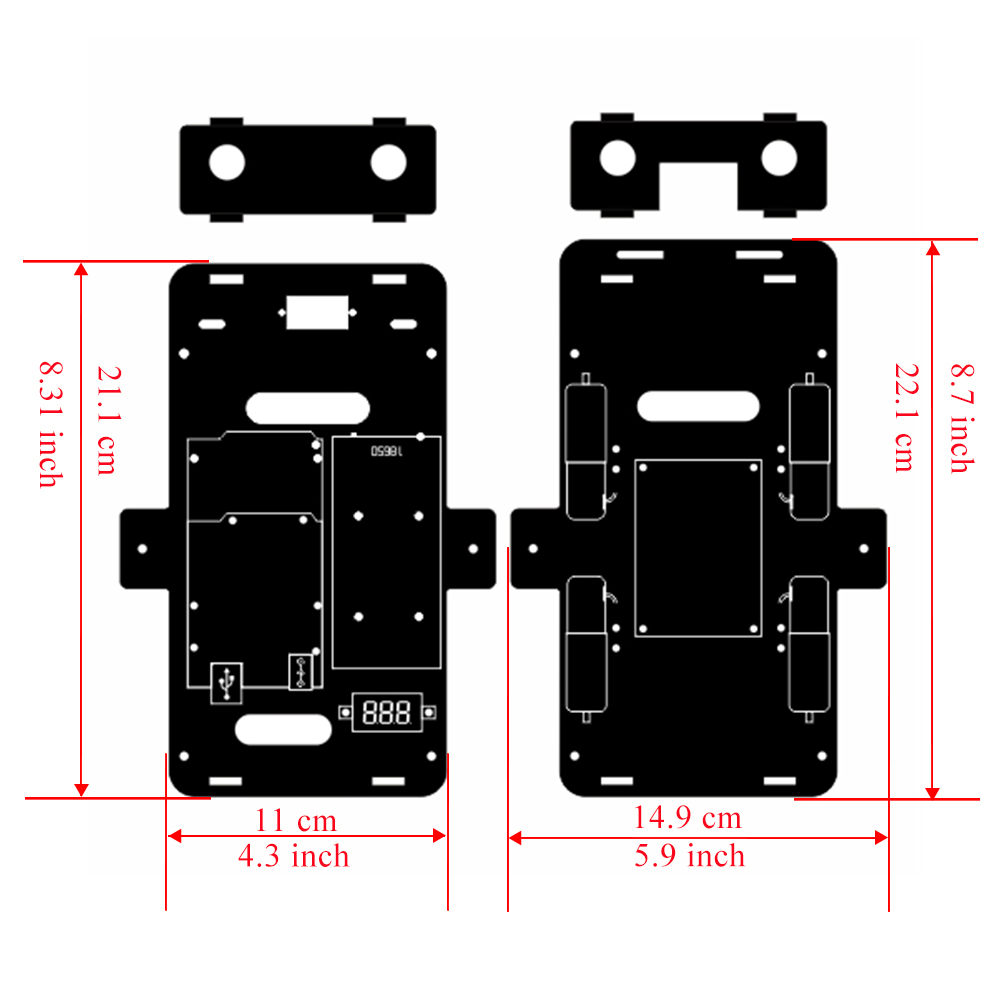
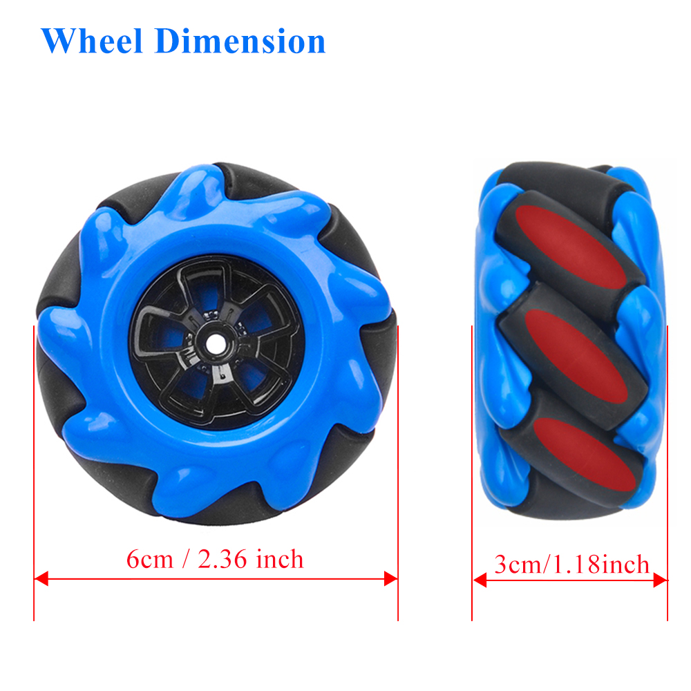
Dimension
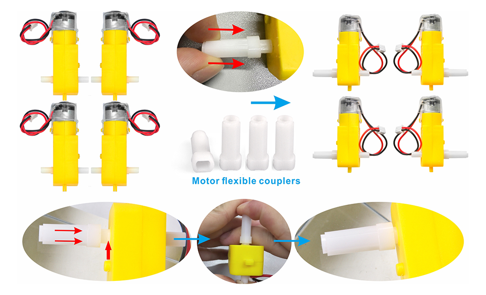
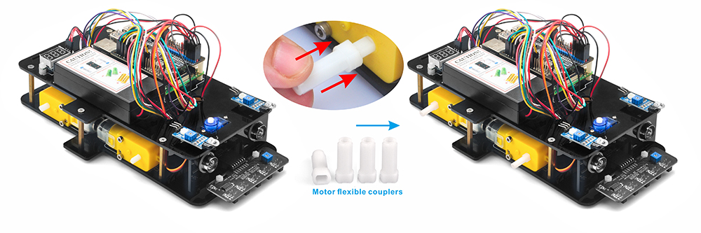
0) Install the white coupling onto the yellow motor following the steps shown in the image. Make sure the coupling is pushed all the way down to the base.
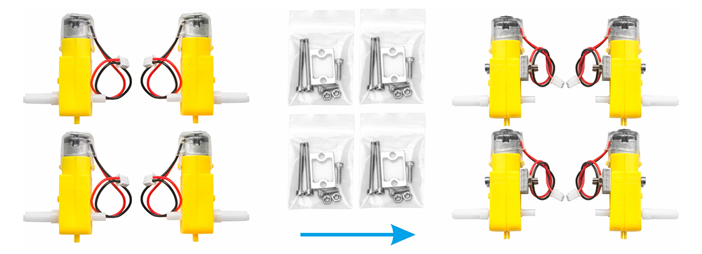
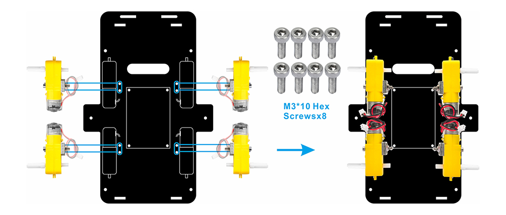
1) Attach the 4 motors using the metal motor holders as shown. (Make sure the motor orientation is correct before installing the metal motor holders.)
2) Secure the 4 motors to the lower car chassis using M3×10 hex screws and a hex screwdriver, as shown in the image. (The screws for this step are included in the metal motor holder package.)
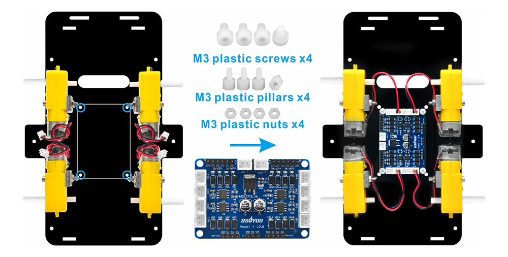
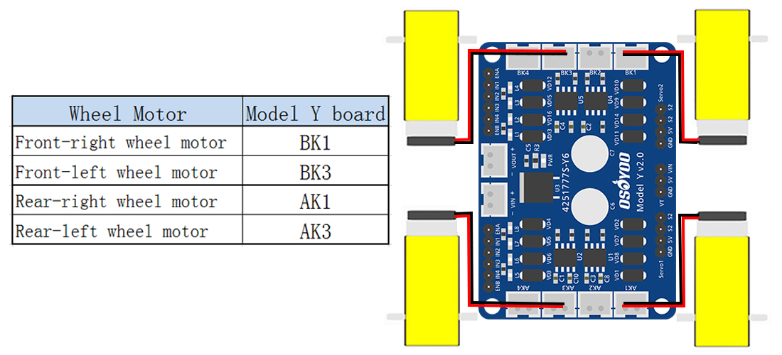
3) Mount the OSOYOO Model Y driver board onto the lower car chassis using 4 M3 plastic screws, plastic pillars, and plastic nuts (it is recommended to install the plastic pillar with the male end facing downward). Then connect the 4 motors to the K1 and K3 sockets on the Model Y motor driver board, as shown in the diagram.
(Make sure the OSOYOO Model Y driver board is installed in the correct orientation.)
There are two installation modes for plastic pillars: A. The male end of the plastic pillar faces downward. B. The male end of the plastic pillar faces upward.
4) Connect the 4 motors to the K1 and K3 sockets on the Model Y motor driver board, as shown in the diagram.
About Model Y V2.0 H-Bridge 4-Channel Motor Driver:
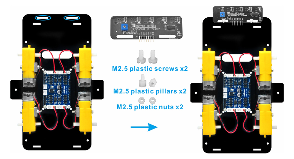
5) Attach the tracking sensor module to the lower chassis using two M3 plastic screws, two M3 plastic pillars, and two M3 plastic nuts (it is recommended to install the plastic pillar with the male end facing upward). Make sure the sensor is securely fixed and properly aligned for accurate functionality.
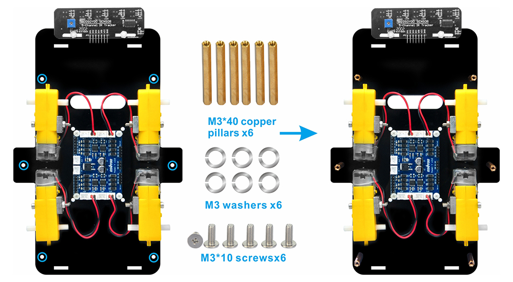
6) Attach six M3×40 copper pillars to the lower chassis using six M3×10 screws and six M3 washers. Make sure the pillars are firmly fixed to provide stable support for the upper chassis.
Slide a washer onto each screw before tightening. A washer distributes screw pressure and improves stability when securing screws into metal pillars.
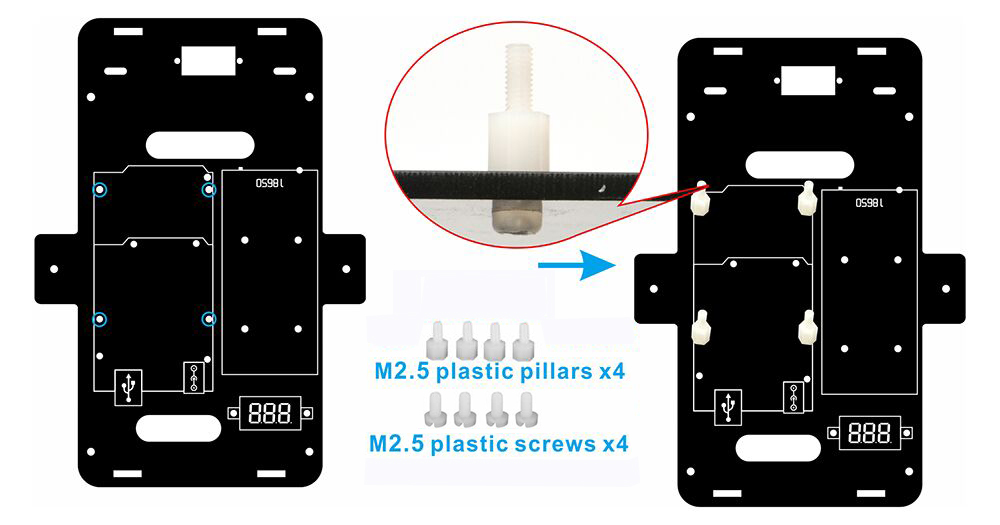
7) The acrylic chassis has dedicated mounting holes for installing the Raspberry Pi board. Install four white plastic M2.5×5+6 standoffs and M2.5×5 screws in these holes as shown in the figure below.
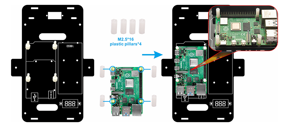
8) Secure the Raspberry Pi 4 board (not included) to the upper chassis using four M2.5×16 plastic pillars.
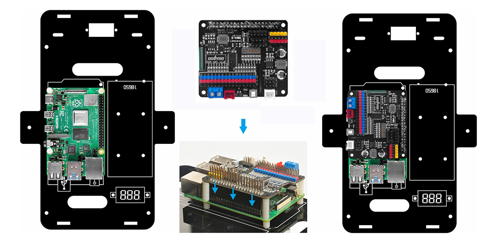
9) Insert the OSOYOO PWM HAT shield onto your Raspberry Pi board.
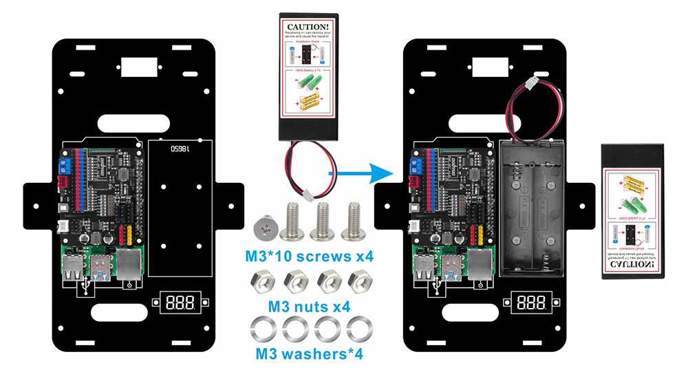
10) Use four M3×10 screws, four M3 nuts, and four M3 washers to attach the battery box to the designated markings on the upper chassis.
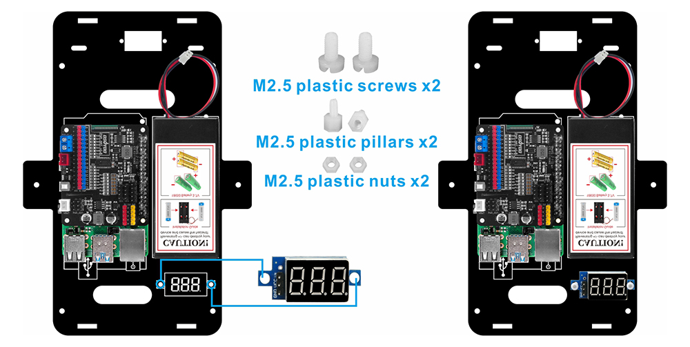
11) Attach the voltage meter to the designated markings on the lower chassis using two M2.5 plastic screws, two M2.5 plastic pillars, and two M2.5 plastic nuts. (It is recommended to install the plastic pillar with the male end facing upward.)
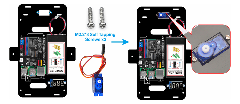
12) Using two M2.2×8 self-tapping screws, mount the SG90 servo motor at the front of the upper chassis.
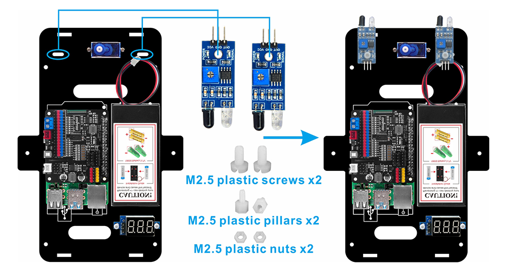
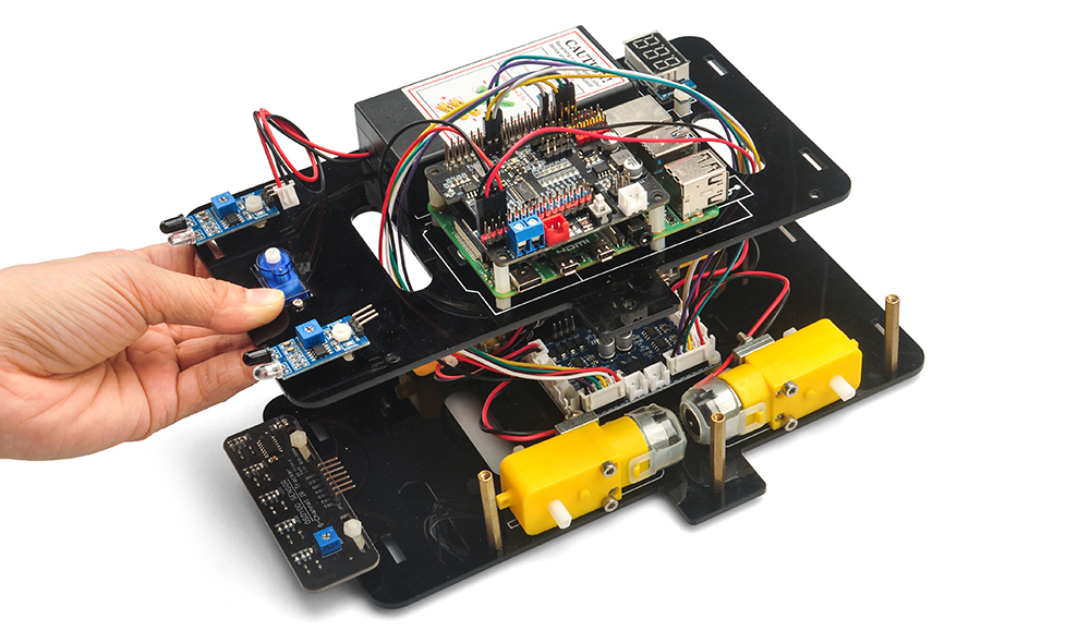
13) Attach two IR distance sensors to the front of the upper chassis using two M2.5 plastic screws, M2.5 plastic pillars, and M2.5 plastic nuts. To secure the sensors tightly, it is recommended to install the plastic pillar with the male end facing upward.
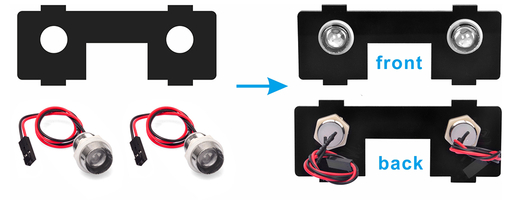
14) Mount two LED lights onto the front barrier plate as shown in the diagram.
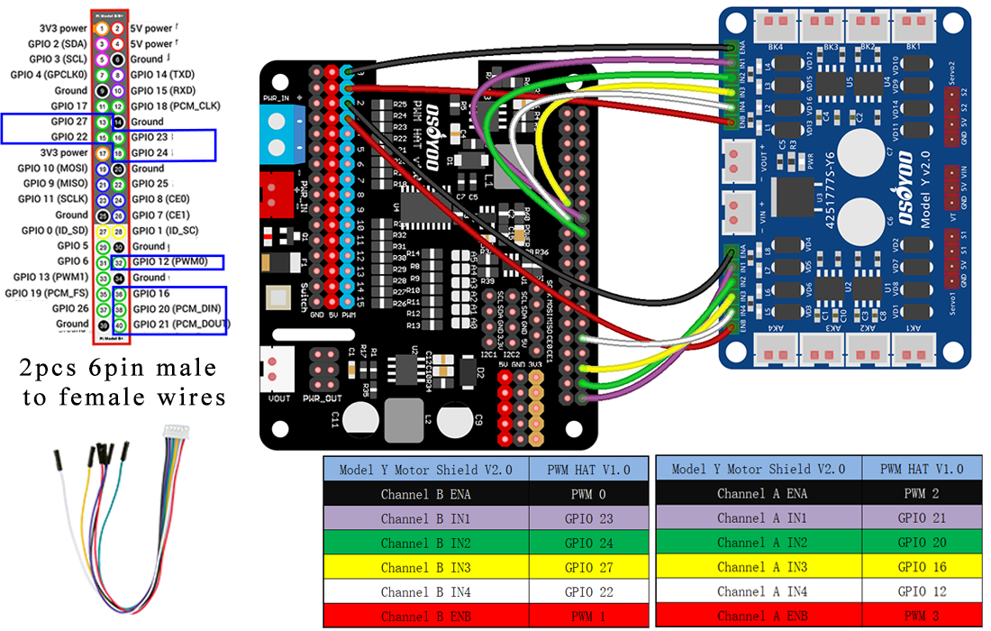
15) Connect the OSOYOO Model Y board to the OSOYOO PWM HAT shield using 2 six-pin female-to-female jumper wires as follows. The 6-pin wires in Area B should pass through the hole near the SG90 servo; the other 6-pin wires in Area A should pass through the hole near the voltage meter.
Caution:
When inserting or removing the 6-pin plug from the Model Y 6-pin male socket, hold the plastic pin holder to do so. Never pull the plug out by the wires, as this will damage them.
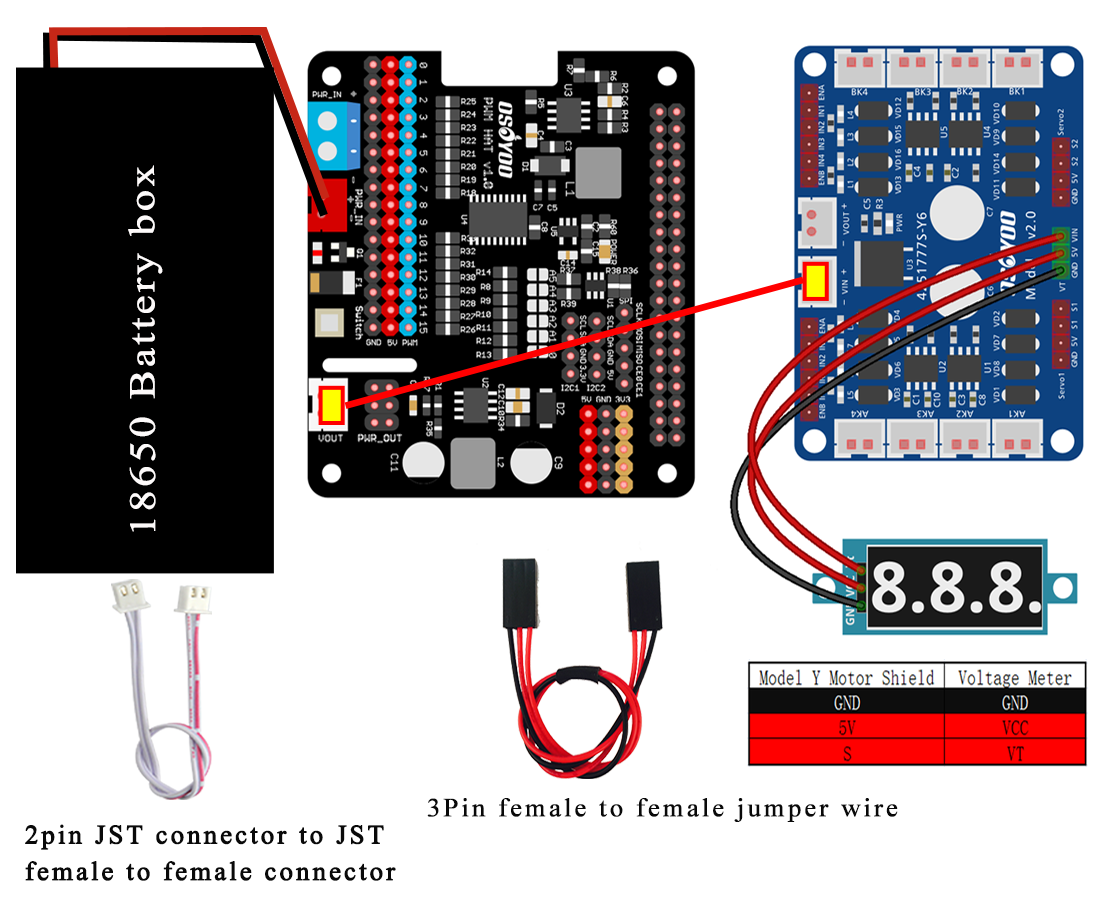
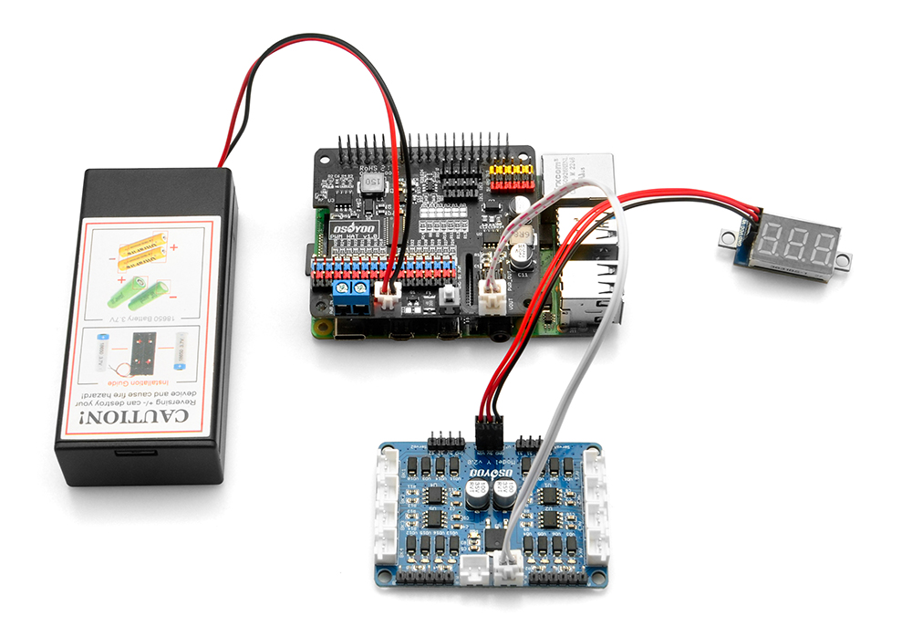
16) Connect the voltage meter to the OSOYOO Model Y board using a 3-pin female-to-female jumper wire as shown in the connection diagram below.
Connect the OSOYOO Model Y board 12V–GND socket to the VIN–GND socket using the OSOYOO 2-pin PnP cable (20 cm), as shown in the following diagram.
Connect the battery box to the VIN–GND socket of the OSOYOO UART WiFi shield according to the connection diagram below.
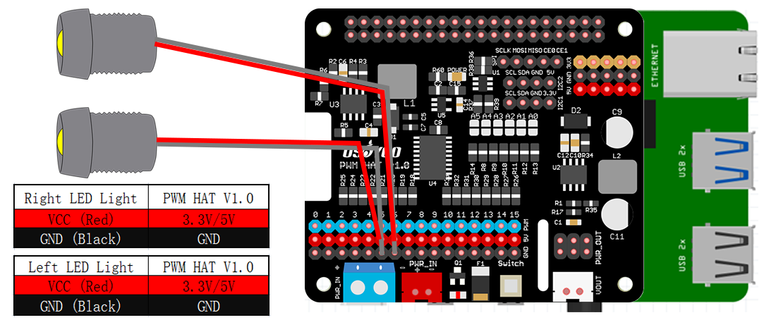
17) Mount 2 LED lights on the front transverse diaphragm.
Connect the red wires (VCC) of the LED lights to the 3.3V or 5V pins, and the black wires (GND) to the GND pins on the OSOYOO PWM HAT shield.
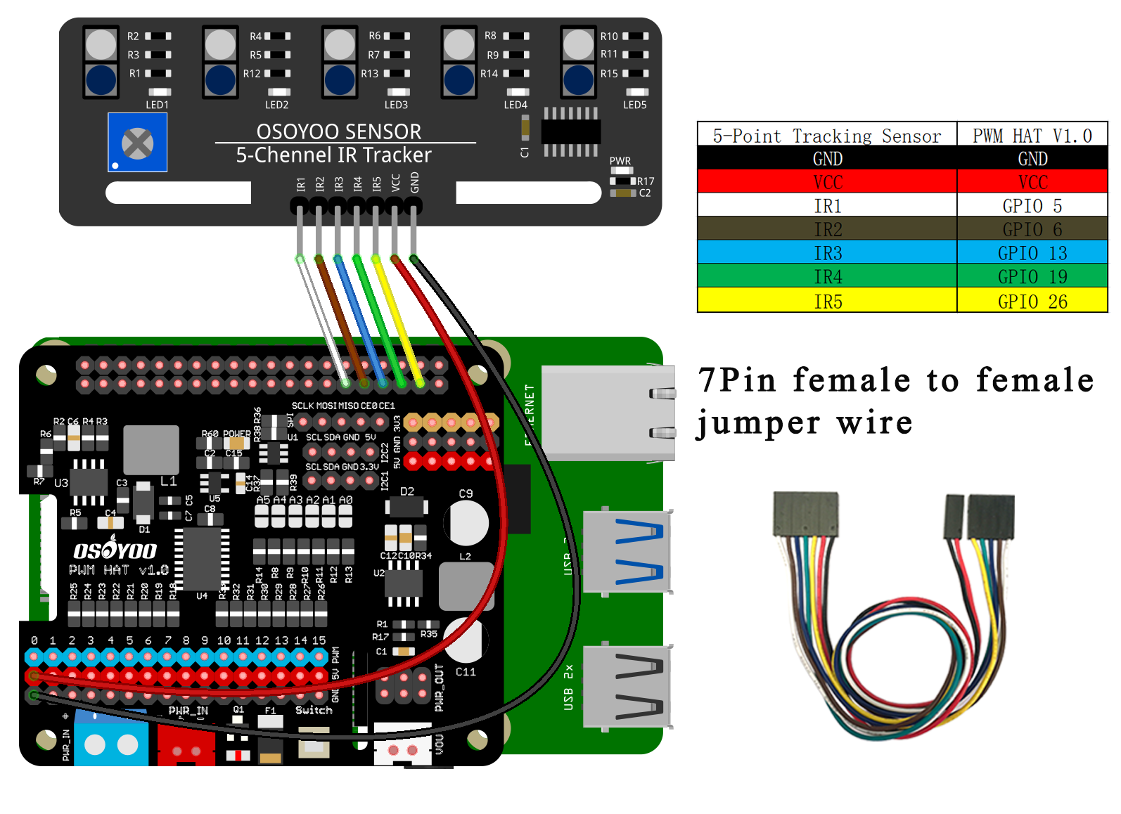
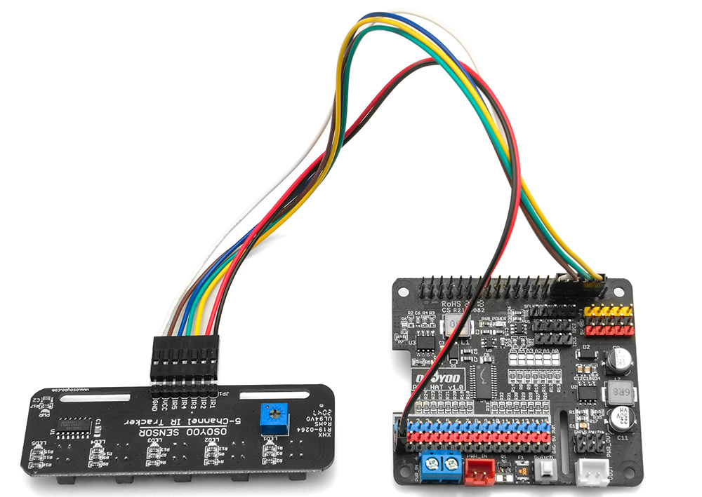
18) Connect the GND–VCC pins of the tracking sensor module to the GND–5V pins on the OSOYOO PWM HAT shield. Connect IR1, IR2, IR3, IR4, and IR5 to GPIO5, GPIO6, GPIO13, GPIO19, and GPIO26 using a 7-pin 25 cm female-to-female cable as shown below.
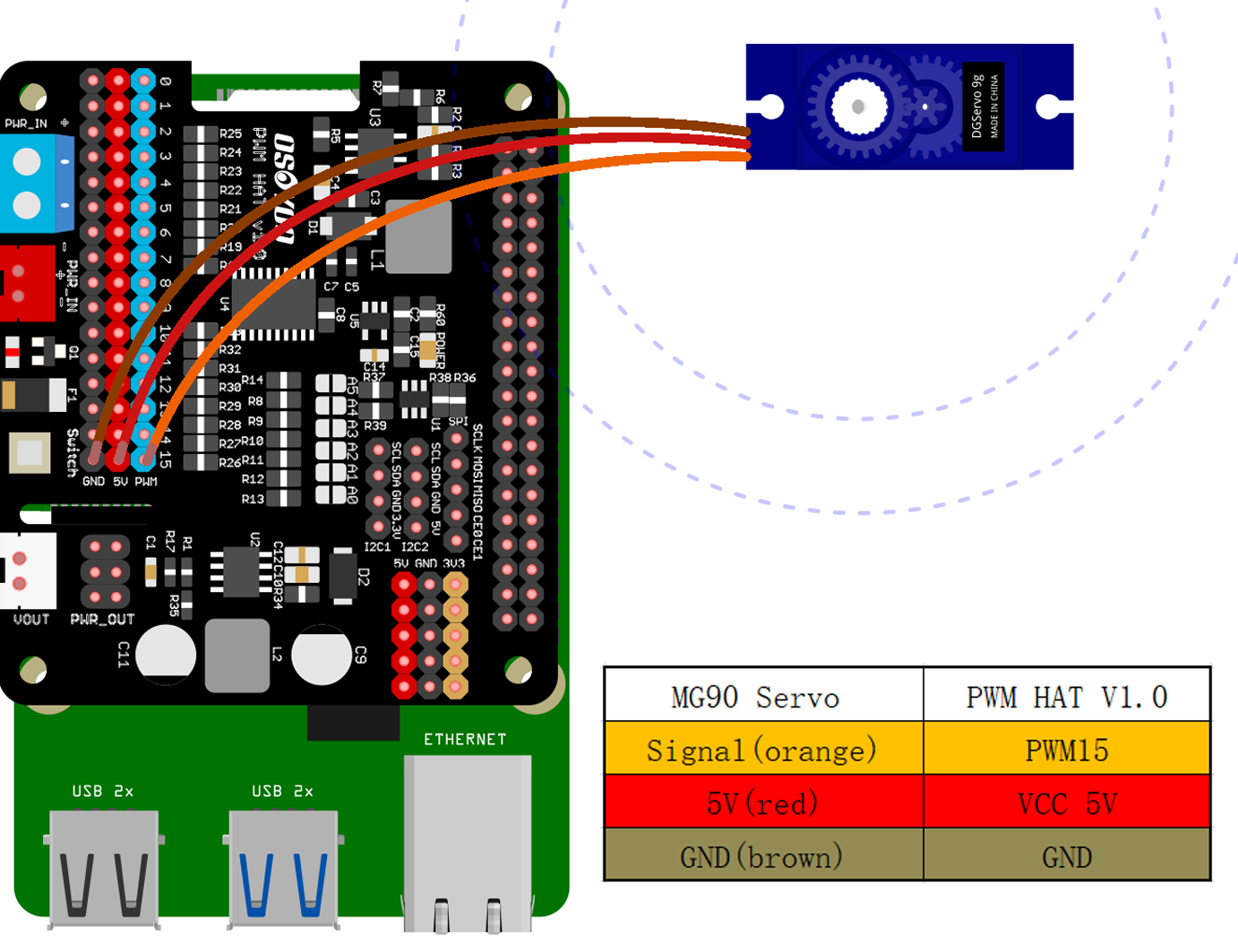
19) Connect the SG90 servo motor, OSOYOO Model Y board, and OSOYOO PWM HAT as shown in the following diagram.
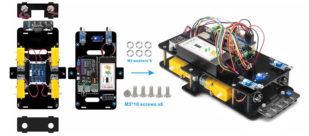
20) Make sure all necessary circuit connections are completed before assembling the upper and lower chassis. Then fix the upper chassis to the lower chassis using 6 M3×10 hex screws.
21) Install 4 flexible couplings and wheels onto the motors using 4 M2.5×20 or M2.6×20 screws. Make sure the white coupling is fully inserted into the bottom of the yellow motor.
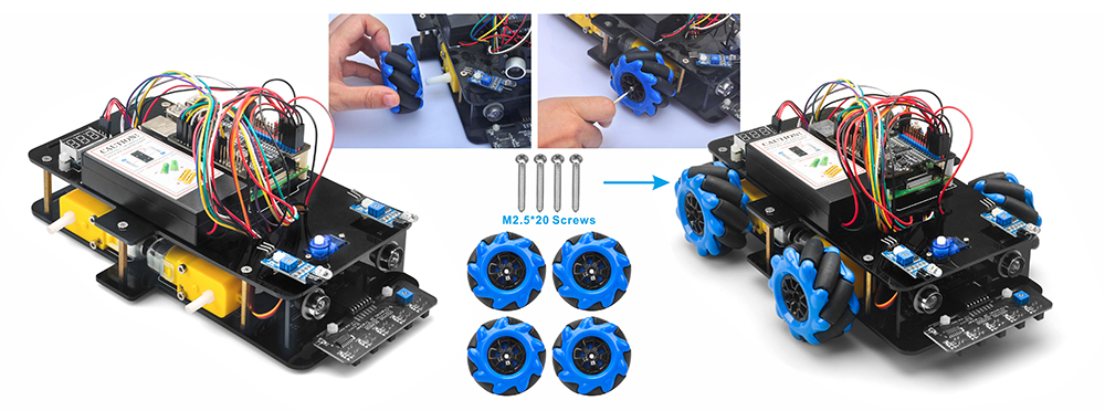
22) Install the 4 wheels onto the motors using 4 M2.5×20 or M2.6×20 screws.
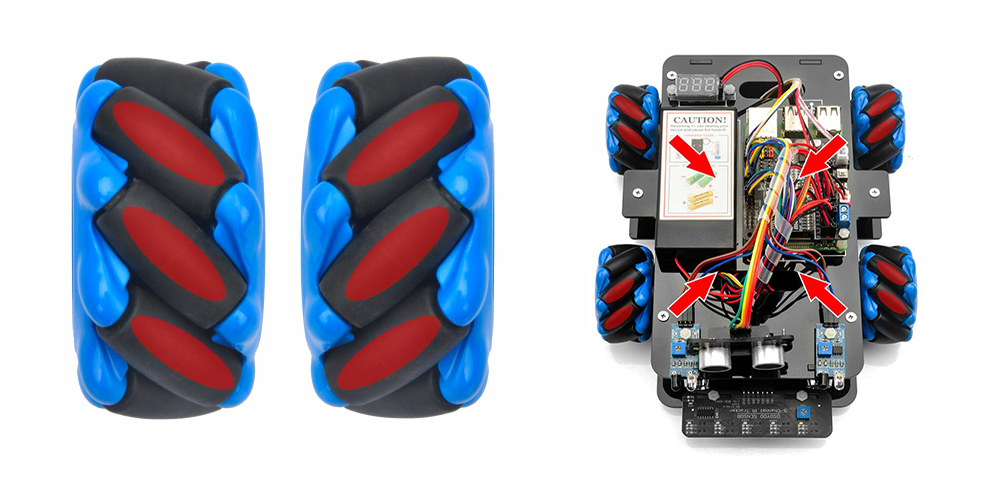
Note: There are two types of wheels. Arrange them so that the rollers angle toward the center of the car when viewed from above.
There are two types of Mecanum wheels — left and right — and the difference between them is the orientation of the rollers. For an A-type Mecanum wheel, as shown below, the rollers are oriented from lower-right to upper-left. The rollers on B-type wheels are installed in the opposite direction.
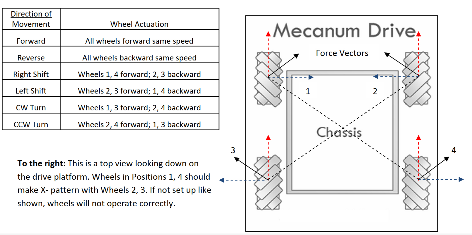
A correct configuration requires each of the four wheels to be positioned so that the rotation axis of each wheel’s top roller points toward the center of the platform. Please note that all dynamic analysis and pre-written code is based on this configuration.
Hardware assembly is now complete. Before inserting the 18650 batteries into the box, you need to upload and run the sample code on your Raspberry Pi first. The next lesson covers this in detail.