In this “Hello World” version lesson, we will install the most important framework in the smart car and program the car to do some simple movements. If you have passed the test movement of this lesson, it means board, voltage meter, motor control module, motors, batteries, chassis and wire connections between these parts are all functioning well.
As your experiments in future lessons are all based on the framework of Lesson One, it is very important to test the installation and sample code in this Lesson properly.
Parts and Devices:
No.
Picture
Device
Qty.
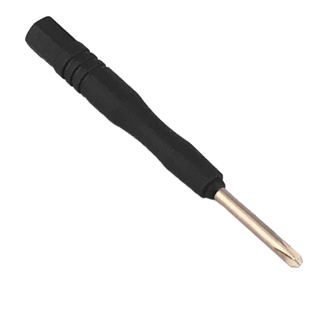
Accessories
Link
1
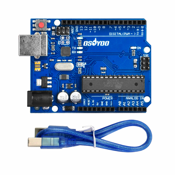
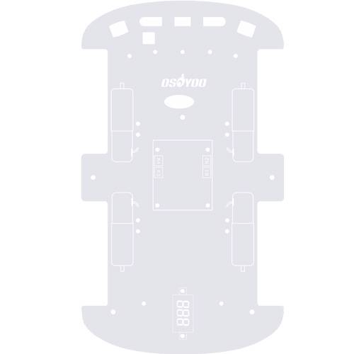
OSOYOO basic board
1
M3 Plastic Screw x 3
M3 Plastic Nut x 4
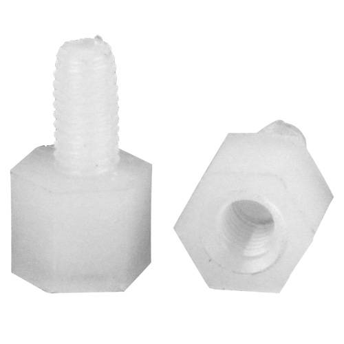
M3 Plastic Pillar x 4
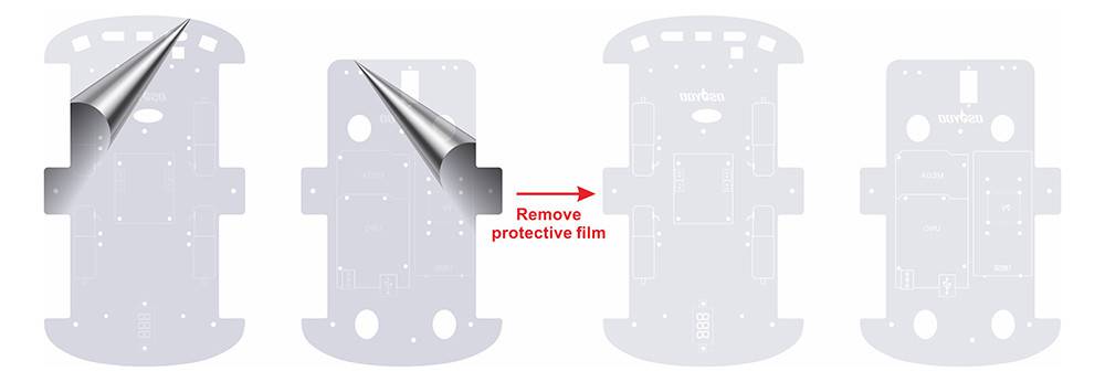
1) Remove the protective film on upper and low car chassis (Each car chassis has one protective film)
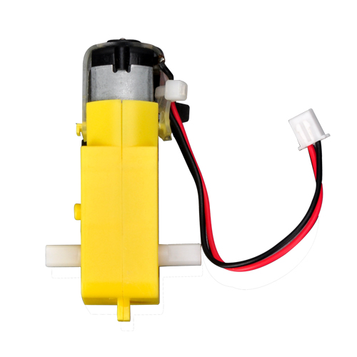
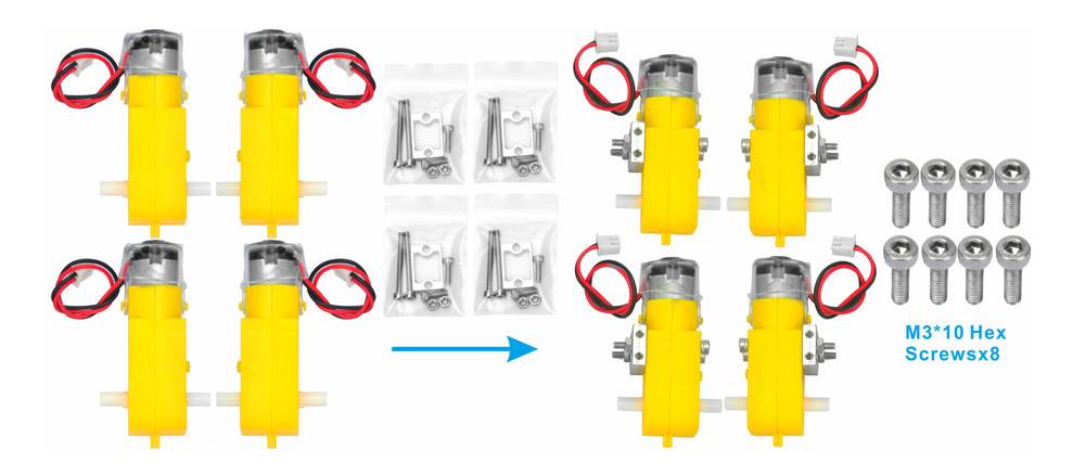
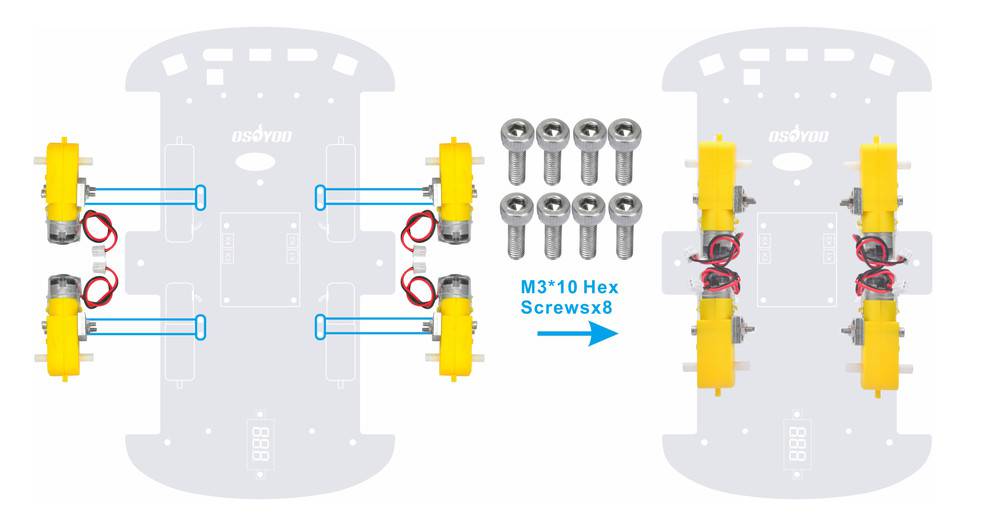
2) fix 4 motors with Metal Motor Holders as follows (Please check the motor direction before installing metal motor holders)
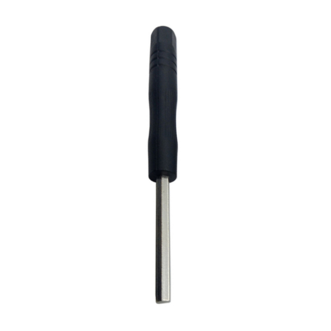
3) Fix 4 motors on lower car chassis with screw M3*10 hex screws via hex screwdriver (screws for this step are in metal motor holder package)
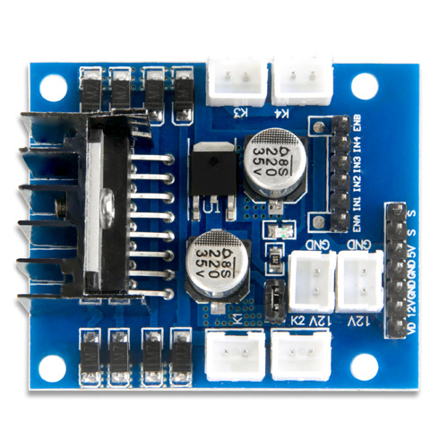
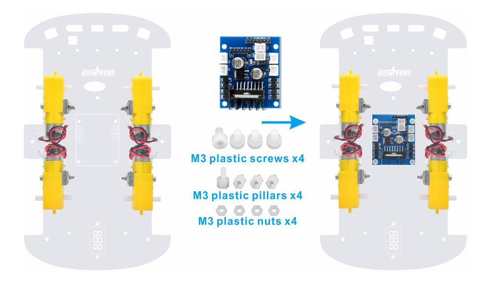
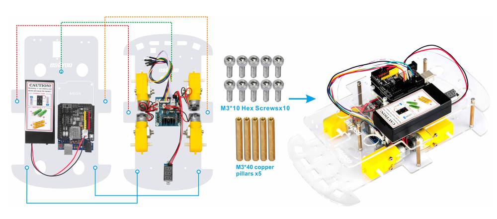
4) Install OSOYOO MODEL X motor driver module to lower car chassis with 4pcs M3 plastic screws, plastic pillars and plastic nuts. (Please make sure you install the OSOYOO MODEL X motor driver module in the correct direction.)
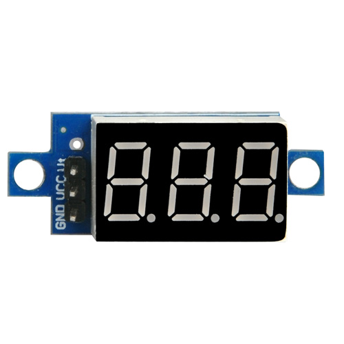
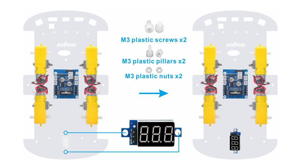
5) Install voltage meter on low car chassis with 2pcs M3 plastic screws, plastic pillars and plastic nuts
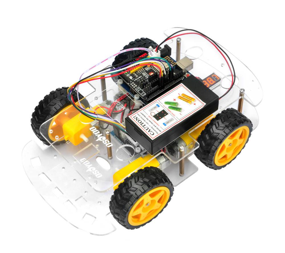
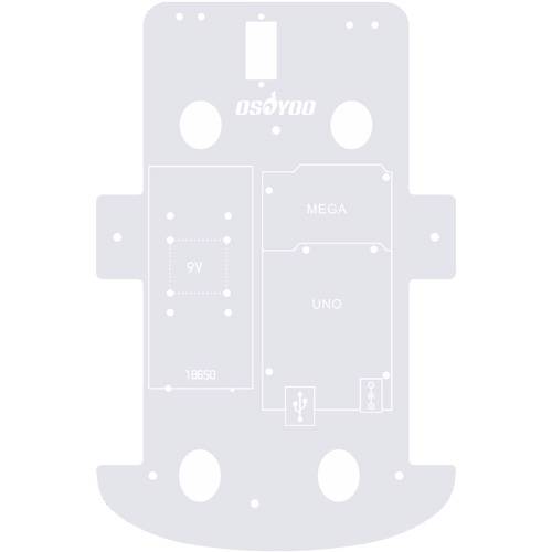
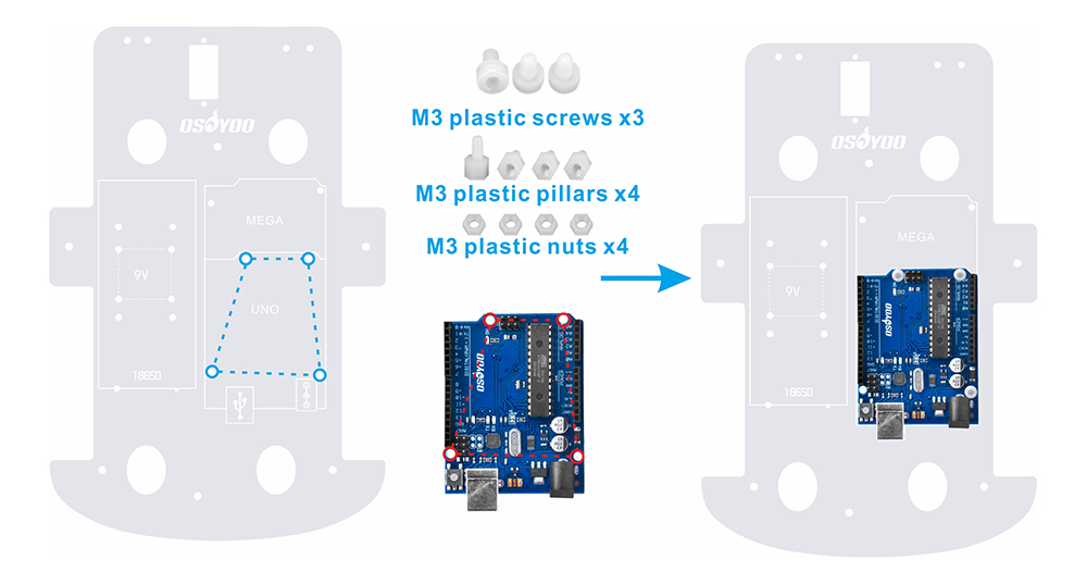
6) Fix OSOYOO basic board on upper car chassis with 4pcs M3 plastic screws, plastic pillars and plastic nuts. (Please install board at the side with printing)
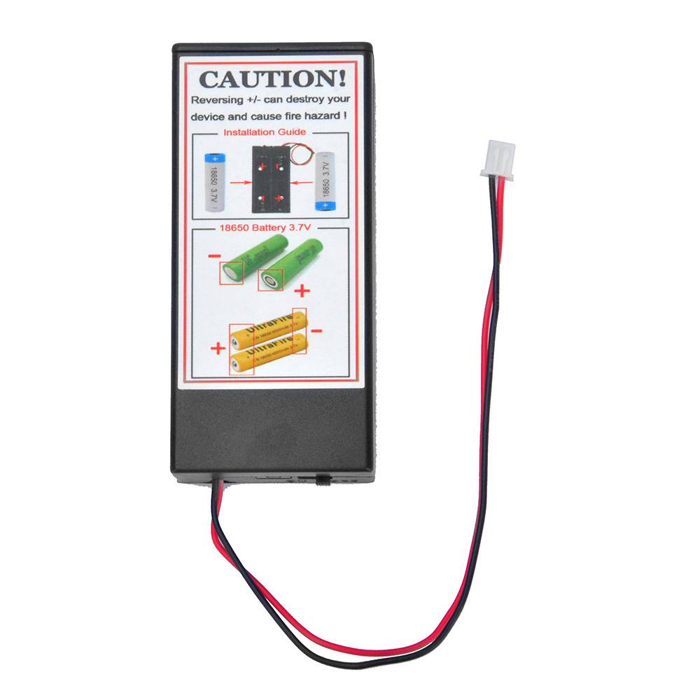
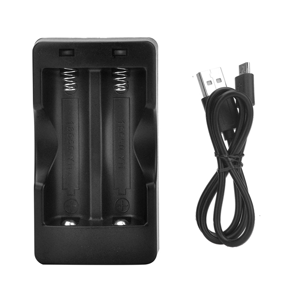
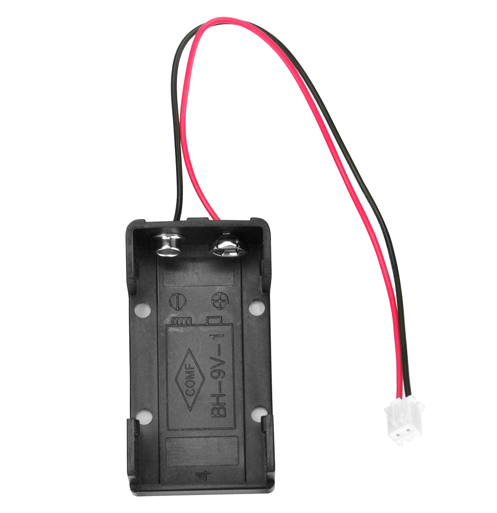
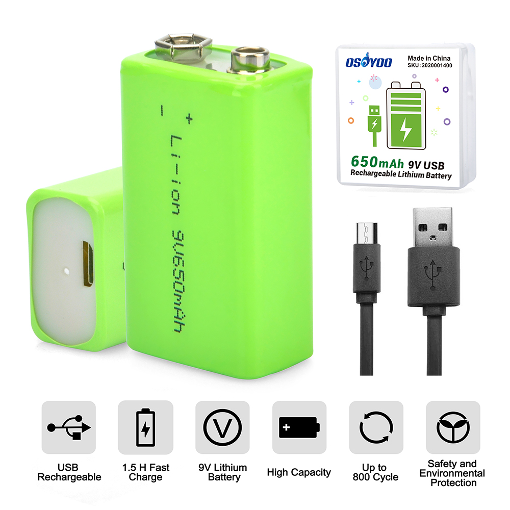
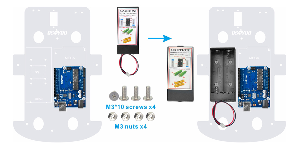
7) There are two kinds of robot car set for you to choose to buy. The one is with 2 battery box (18650 battery box and 9V battery box), and the other one is with 1 pair 18650 batteries and 1 piece battery charger for 18650. We recommend to use 18650 batteries as the power. If you want to use 9V battery as the power, please use rechargeable 9V battery. Don’t use Carbon zinc battery, as this can’t provide enough current for the robot car.
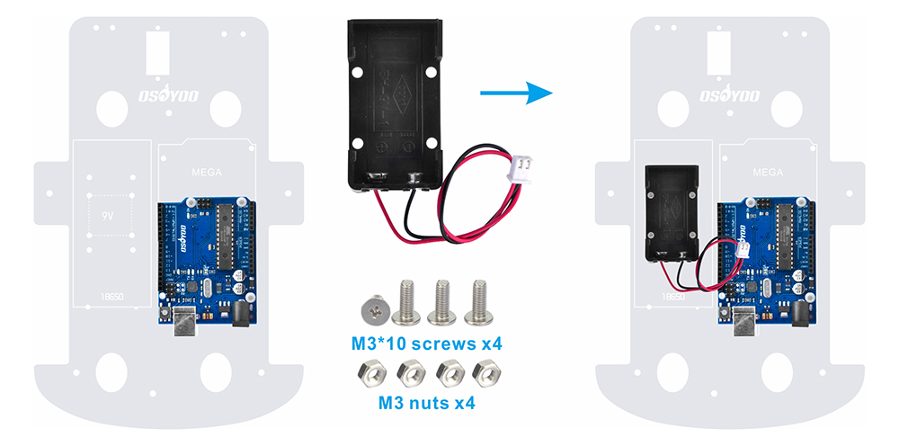
A) Fix this Battery Box on upper chassis with 4pcs M3 x 10 screws and M3 nuts.
B) Please install this Battery Box on upper chassis with 4pcs M3 x 10 screws and M3 nuts. (these are the same as screws and nuts for 18650 battery box. If you don’t get 9V battery case, please ignore this step).
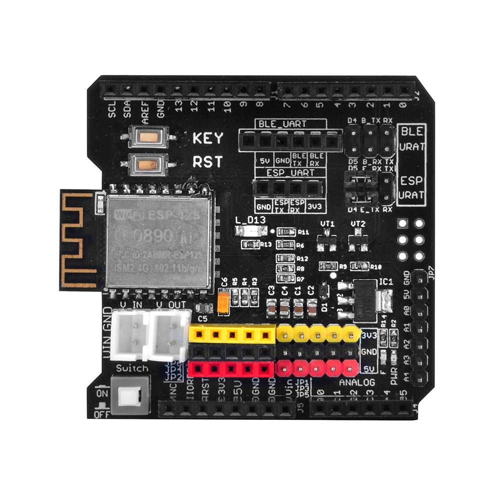
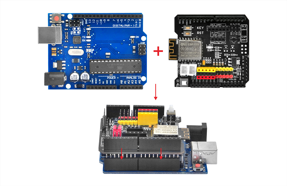
7) Insert OSOYOO Uart Wi-Fi shield V1.3 onto your board
✅ This tutorial was written for the OSOYOO V2.1 Robot Car Kit
All 8 lessons, sample code, and circuit diagrams on this page are designed specifically for this kit.
Buy direct from OSOYOO Store and save 10% — plus get free shipping on orders over $70.
OSOYOO V2.1 Robot Car Kit
🔋 With battery & charger: $61.02 $67.80
— code ROBOTCAR10
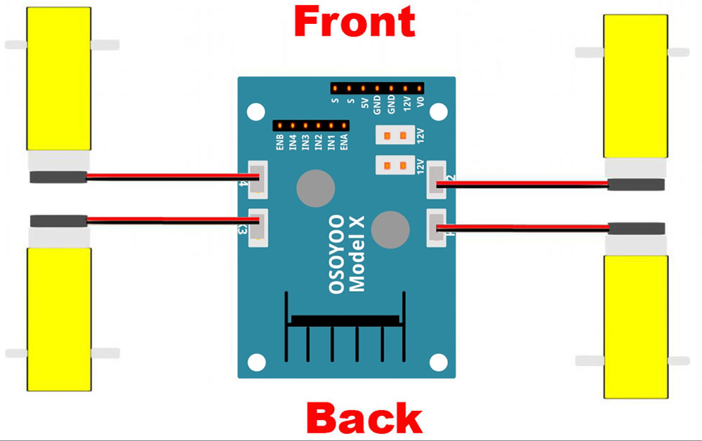
1) Connect 4 motors to OSOYOO MODEL X motor driver module K1 to K4 sockets as per following graph:
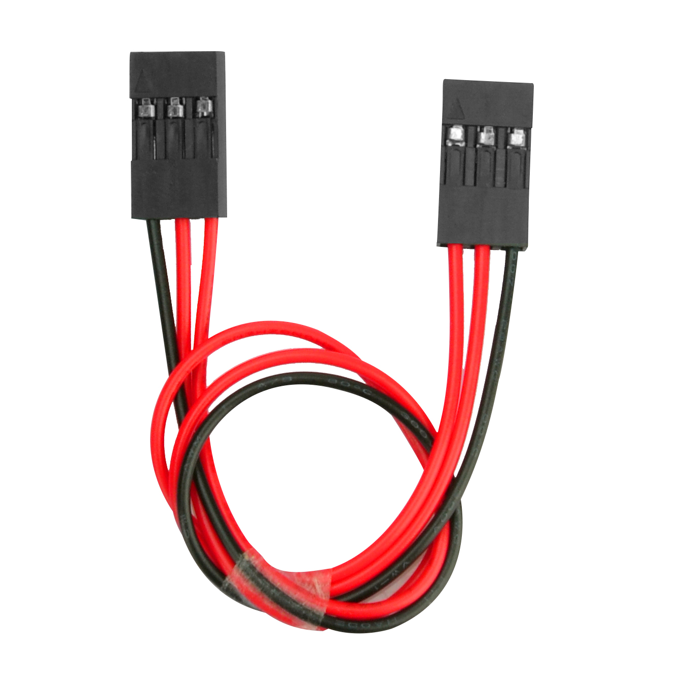
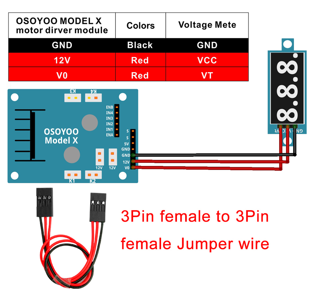
2) Connect Voltage Meter to OSOYOO MODEL X motor driver module with 3pin female to female jumper wire as below connection diagram
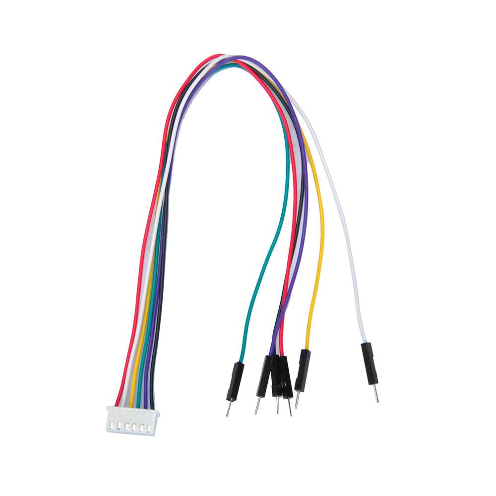
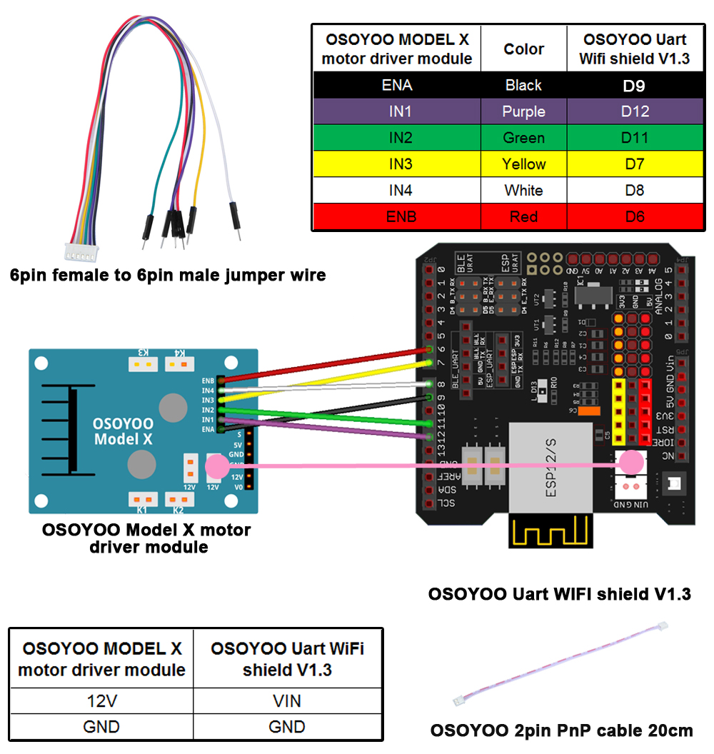
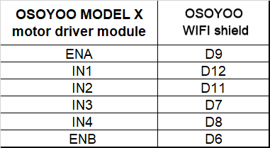
3) Connect OSOYOO MODEL X motor driver module 6 control pins to OSOYOO Uart Wi-Fi shield V1.3 D6, D7, D8, D9, D11, D12 with 6pin male to 6pin female jumper wire, and 12V-GND socket to VIN-GND socket with OSOYOO 2pin PnP cable 20 cm as per following graph
Caution:
When insert/remove this 6-pin plug into Model X 6-pin male socket, please hold the plastic pin-holder to do operation. Never drag the wires to pull the plug out of the socket, otherwise it will damage the wires.
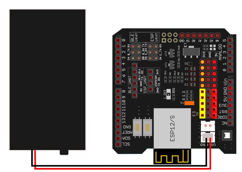
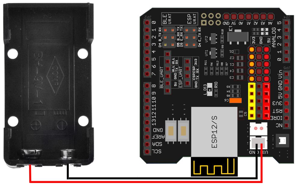
4) Connect battery box (battery box for 18650 batteries or for 9V battery) to VIN-GND socket of OSOYOO Uart Wi-Fi shield V1.3 according to connection diagram
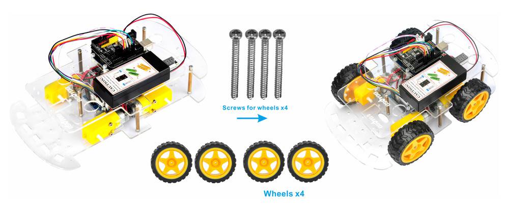
5) Connect upper chassis to lower chassis with five copper pillars and fix copper pillars with 10pcs M3*10 hex screws, then install 4 wheels onto the motors. (Please loosen the screws on the wheel if some of the wheels don’t move)
Now hardware installation is almost down. Before we install 18650 batteries into the box, we need to burn the sample code into the board First.
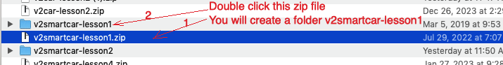
Step 2: Download Lesson One sample code from https://osoyoo.com/driver/v2smartcar-lesson1.zip,unzip the download zip file smartcar-lesson1.zip, you will see a folder called v2smartcar-lesson1.
Double Click the folder name v2smartcar-lesson1, you will see v2smartcar-lesson1.ino file
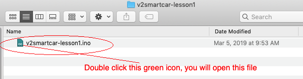
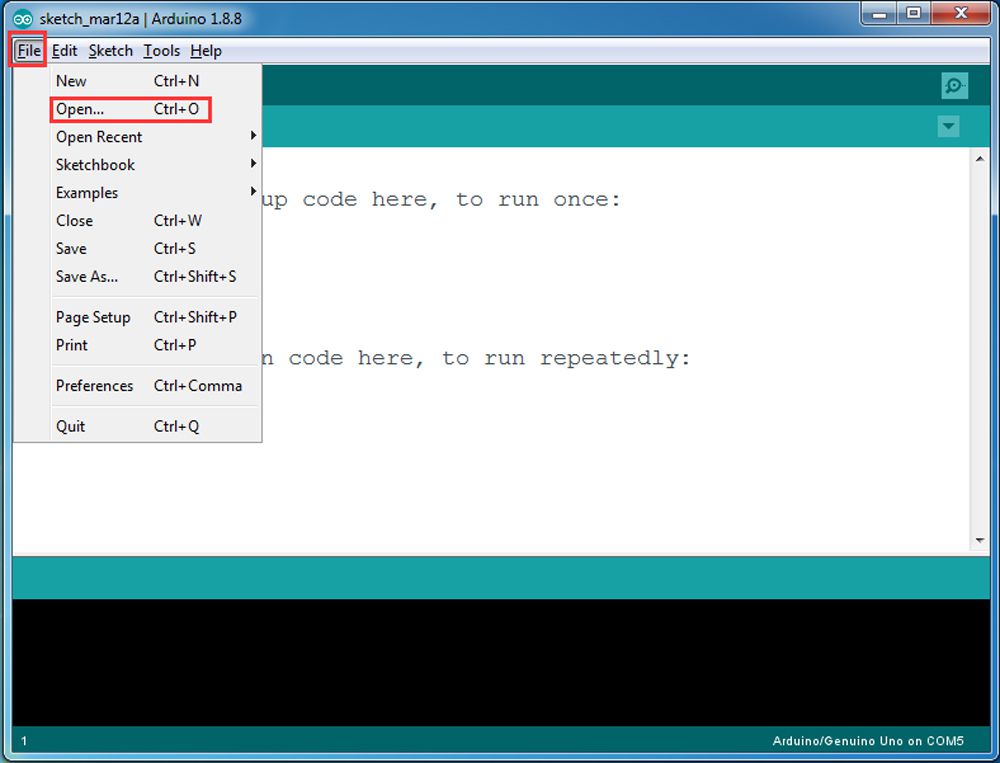
Step 3: Double Click “v2smartcar-lesson1.ino” in smartcar-lesson1 folder to open this file,
load the code into board.
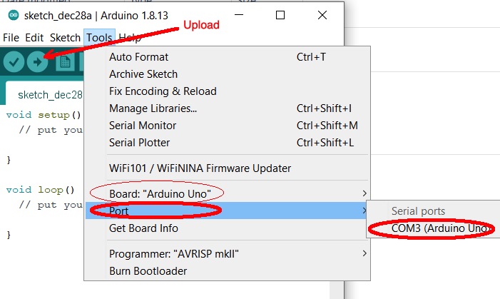
Step 4: Choose corresponding board/port for your project, upload the sketch to the board.
Final Testing:
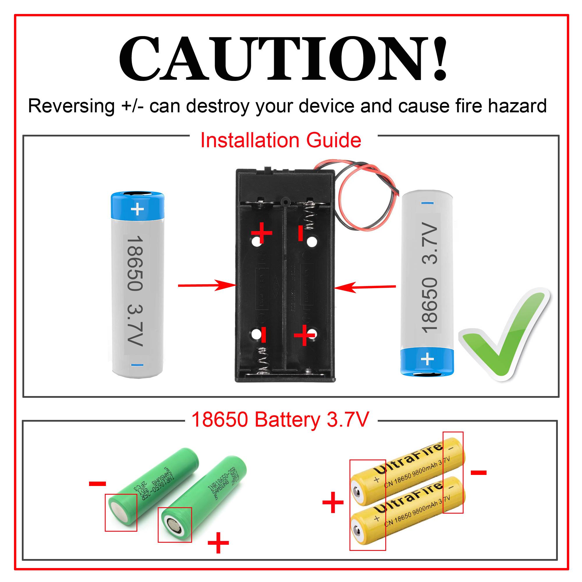
Note:
1) Recommend 18650 batteries as these batteries can make the car run smoothly.
2) The 18650 batteries we used in lessons are around 65 mm (2.56 inch) long, without an internal protection circuit.
3) Check the box instruction and make sure polar direction is correct, otherwise it can destroy your device and cause fire hazard.
Please install your 18650 batteries in battery box for 18650 as per following instruction:
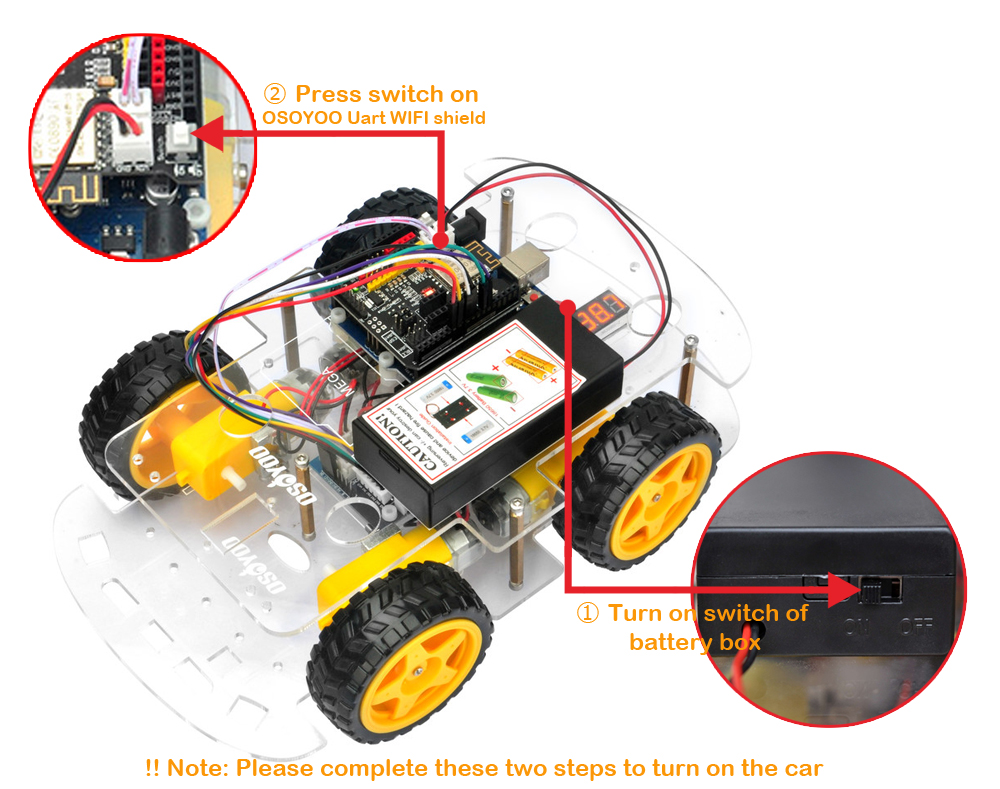
Disconnect robot car from PC, put battery into battery box. When you put the car on the ground and turn on the switch on OSOYOO Uart Wi-Fi shield V1.3 and the switch on battery box if you install battery box for 18650, the car should go forward 2 seconds, then go backward 2 seconds, then left turn for 2 seconds, then right turn for 2 seconds, then stop. (If the car does not move as per above-mentioned result, you should check your wire connection, battery voltage (must over 7.2v).)
Motor Control Logic Table
IN1 and IN2 pins of the Model X board(H-Bridge) control the rotation direction of motors K1 and K2 (which move in synchronization).
The ENA pin PWM value controls the rotation speed of K1 and K2.
Similarly, IN3 and IN4 control the rotation direction of motors K3 and K4 (which move in synchronization).
The ENB pin PWM value controls the rotation speed of K3 and K4
Input Pins
Logic Level
Motor Group
Direction
IN1 / IN2
HIGH / LOW
K1/K2
Move Forward
IN1 / IN2
LOW / HIGH
K1/K2
Move Backward
IN3 / IN4
HIGH / LOW
K3/K4
Move Forward
IN3 / IN4
LOW / HIGH
K3/K4
Move Backward
Troubleshooting
If, after running the Lesson 1 code, you notice that one side wheels are not turning, or one side wheels can only move forward but not backward, or only backward but not forward, the issue is likely a loose or broken wire in the 6-pin cable connecting to the Model X board.
Here is the solution:
Step 1: Disconnect the 6-pin cable that connects the Model X board and the Arduino board.
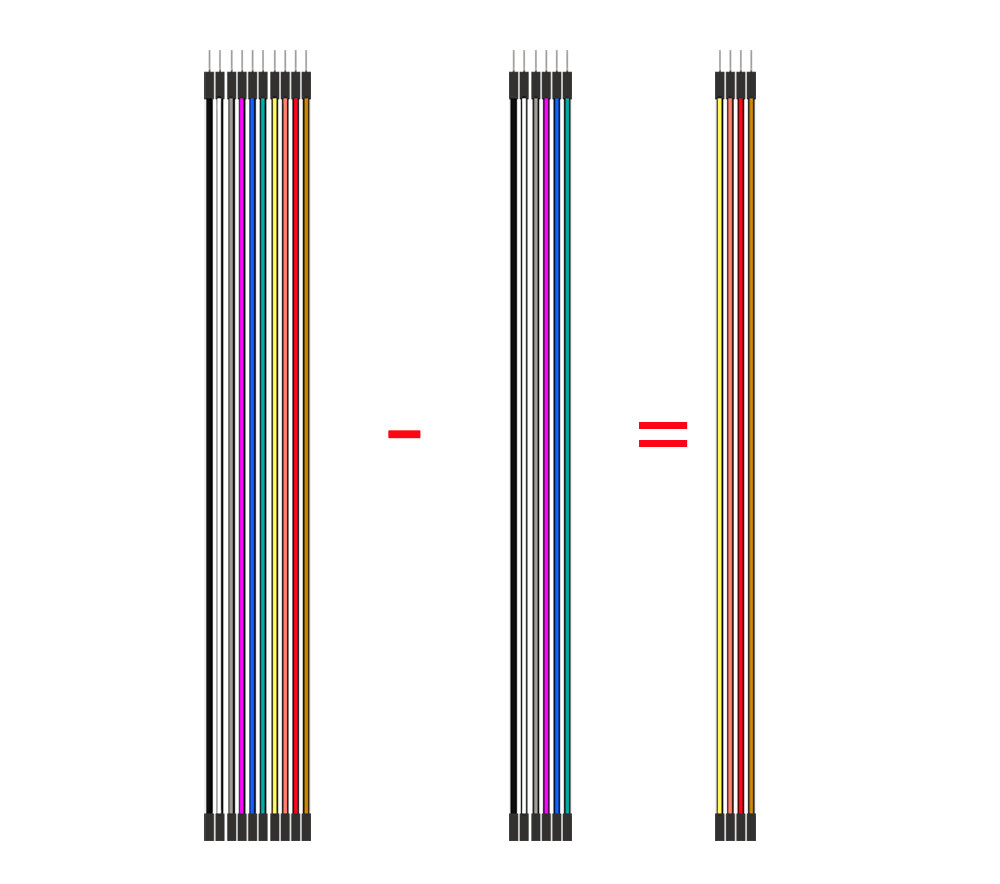
Step 2: Locate six (6) single spare Female-to-Male jumper wires from your kit (any color is fine).
Step 3: Use these six single jumper wires to manually reconnect the Model X pins (ENA, IN1, IN2, IN3, IN4, ENB) to the corresponding pins on the Arduino as per previous model x wire map
Step 4: Retest the Lesson 1 code to see if the issue is resolved. If the problem still exists, you can send your problem detail to [email protected] and our tech support team will help you.
🤖 Start building your V2.1 Robot Car today
Official kit for this tutorial · WiFi + Bluetooth + 8 project lessons included
Use exclusive reader code ROBOTCAR10 for 10% off — buy direct and save vs Amazon
I got a email from [email protected] with a photo. Is it from you.
If not, please take a photo about the connections to my email address: [email protected].
Thanks!
I’m not quite sure what you mean. If you want to reset the robot, you can press the reset button on the motherboard; if you want to upload a different code to the robot, you may need to connect a computer and upload the new code through the Arduino IDE。。。
hello, i need help with the program upload to the car. i keep getting error stating the upload failed. i have checked all wiring and don’t see any mistakes. any suggestions? (email:[email protected])
I recently bought model-3 robot car kit for Arduino.
I have completed first stage hardware build and am trying to load lesson #1 sketch.
I am using a sony Vaio laptop with windows 10 Pro.I did the following steps
Arduino IDE downloaded
Lesson 1 .zip downloaded
Lesson 1 sketch loads correctly to the IDE
I connected USB with the robot car. It looks OK with a solid green and flashing blue LED
in the IDE TOOLs I select Arduino UNO
In IDE TOOLS I selected port COM3 (I only have choice of COM3 or COM4)
In IDE SKETCH I upload
…at the bottom of the IDE screen I get at first green progress bar and information on number of bytes memory used.
This report would have more information with
“Show verbose output during compilation”
option enabled in File -> Preferences.
I then went to the recommended resource to fix the problem and did the following
Windows device manager
PORTS – I looked here and Arduino is not identified
Universal Serial Bus Controllers – I looked here and Arduino is not identified
The layout of the information is not the same as shown in the website here “https://support.arduino.cc/hc/en-us/articles/4407830972050-Find-and-stop-process-blocking-a-port”
1. Please confirm whether the LED on board flash or not, when you press the reset button. If this led flash, it means the boot loader works well.
2. Please install the lastest version of IDE : https://www.arduino.cc/en/Main/Software?setlang=en
3. Please open IDE, and then choose processor: ATmega328p(Old bootloader)
4. Please confirm you don’t install bluetooth module
5. Try to use USB2.0 port to upload the code
6. please use other USB cable and try again
7. Uninstall the CH340 driver and then install new driver from http://www.osoyoo.com/driver/smarthome/7/CH340_341.rar
Hi! I recently set up the car with my son, and we have completed Lesson 1. When we tested…the car only moved backwards, and occasionally forward. But, if I pick it up and look at the wheels, it begins to execute the correct code, and tries to forward, reverse, turn left, then right. It’s almost like the pressure on the wheels affect how it is running. Any help would be greatly appreciated! Thanks!
Hi, please check the voltage of the battery or recharge the battery and try it again.
What’s more, there are different directions of the wheels, please install the wheels in correct direction.
If all doesn’t work, please take a video and send to my email address: [email protected]
Thanks and best regards!
Arduino in picture example in these instructions are not up to date and COM3 port doesn’t exist or is not supported anymore also there are errors in the scratch here:
We have followed lesson 1 and built the car and uploaded the code however the car does not move. The voltmeter does not light up – we have checked all the connection. Any help would be greatly appreciated!!
Hello,
Started to use Model N0. 20190005000 kit. Lesson 1 the car is going backwards first, then forward, left and right. Could you please help with this issue – For advance it is going backwards and for reverse it is going forward.
My name is Quan. I purchased your robot from Amazon, and I have encountered a few issues with the coding. I would like my robot to use the ultrasonic sensor to detect obstacles. When it encounters obstacles, I want it to turn right or left to avoid them and continue moving. However, I am having difficulty with the coding. I hope you can assist me.
After putting the code in only the left two motors run the ones on the right don’t do anything but if I switch their connections I get the opposite effect. Is it a dodgy motors driver module
When running the program :
go_Advance();//Forward ==> OK
go_Back();//Reverse ==> Right back only
go_Left();//Turn left ==> Right forward only
go_Right();//Turn right ==> OK
stop_Stop();//Stop
It means that the left motors can’t go back. Please change the wires from Model X to Wifi shield, and exchange the right motors with left motors. If the issue accours again, please contact with my email: [email protected]
I am returning to this robot. I have completed Lesson 1. When I place robot on ground and switch on, it makes one circle, in reverse, to the right. All connections have been checked and are correct.
Any suggestions?
Regards, James.
based on your description, the 6pin cable connecting model_x board to wifi shield might have problem. please use 6 single pc wire to replace that 6pin cable and try again.


Hi,
I connected everything per the tutorial and downloaded lesson 1 code, but car is not moving.
I got a email from [email protected] with a photo. Is it from you.
If not, please take a photo about the connections to my email address: [email protected].
Thanks!
The same is happening to me
Hi!
How can I reset from the fabric the robot car?
Thanks in advance.
I’m not quite sure what you mean. If you want to reset the robot, you can press the reset button on the motherboard; if you want to upload a different code to the robot, you may need to connect a computer and upload the new code through the Arduino IDE。。。
hello, i need help with the program upload to the car. i keep getting error stating the upload failed. i have checked all wiring and don’t see any mistakes. any suggestions? (email:[email protected])
Please paste the error and send to my email address: [email protected].
Please help me.
I recently bought model-3 robot car kit for Arduino.
I have completed first stage hardware build and am trying to load lesson #1 sketch.
I am using a sony Vaio laptop with windows 10 Pro.I did the following steps
Arduino IDE downloaded
Lesson 1 .zip downloaded
Lesson 1 sketch loads correctly to the IDE
I connected USB with the robot car. It looks OK with a solid green and flashing blue LED
in the IDE TOOLs I select Arduino UNO
In IDE TOOLS I selected port COM3 (I only have choice of COM3 or COM4)
In IDE SKETCH I upload
…at the bottom of the IDE screen I get at first green progress bar and information on number of bytes memory used.
The error message generated is here..
Arduino: 1.8.19 (Windows 10), Board: “Arduino Uno”
Sketch uses 1442 bytes (4%) of program storage space. Maximum is 32256 bytes.
Global variables use 9 bytes (0%) of dynamic memory, leaving 2039 bytes for local variables. Maximum is 2048 bytes.
avrdude: stk500_recv(): programmer is not responding
avrdude: stk500_getsync() attempt 1 of 10: not in sync: resp=0xd4
avrdude: stk500_recv(): programmer is not responding
avrdude: stk500_getsync() attempt 2 of 10: not in sync: resp=0xd4
avrdude: stk500_recv(): programmer is not responding
avrdude: stk500_getsync() attempt 3 of 10: not in sync: resp=0xd4
avrdude: stk500_recv(): programmer is not responding
avrdude: stk500_getsync() attempt 4 of 10: not in sync: resp=0xd4
avrdude: stk500_recv(): programmer is not responding
avrdude: stk500_getsync() attempt 5 of 10: not in sync: resp=0xd4
avrdude: stk500_recv(): programmer is not responding
avrdude: stk500_getsync() attempt 6 of 10: not in sync: resp=0xd4
avrdude: stk500_recv(): programmer is not responding
avrdude: stk500_getsync() attempt 7 of 10: not in sync: resp=0xd4
avrdude: stk500_recv(): programmer is not responding
avrdude: stk500_getsync() attempt 8 of 10: not in sync: resp=0xd4
avrdude: stk500_recv(): programmer is not responding
avrdude: stk500_getsync() attempt 9 of 10: not in sync: resp=0xd4
avrdude: stk500_recv(): programmer is not responding
avrdude: stk500_getsync() attempt 10 of 10: not in sync: resp=0xd4
Problem uploading to board. See https://support.arduino.cc/hc/en-us/sections/360003198300 for suggestions.
This report would have more information with
“Show verbose output during compilation”
option enabled in File -> Preferences.
I then went to the recommended resource to fix the problem and did the following
Windows device manager
PORTS – I looked here and Arduino is not identified
Universal Serial Bus Controllers – I looked here and Arduino is not identified
The layout of the information is not the same as shown in the website here “https://support.arduino.cc/hc/en-us/articles/4407830972050-Find-and-stop-process-blocking-a-port”
1. Please confirm whether the LED on board flash or not, when you press the reset button. If this led flash, it means the boot loader works well.
2. Please install the lastest version of IDE : https://www.arduino.cc/en/Main/Software?setlang=en
3. Please open IDE, and then choose processor: ATmega328p(Old bootloader)
4. Please confirm you don’t install bluetooth module
5. Try to use USB2.0 port to upload the code
6. please use other USB cable and try again
7. Uninstall the CH340 driver and then install new driver from http://www.osoyoo.com/driver/smarthome/7/CH340_341.rar
Hi! I recently set up the car with my son, and we have completed Lesson 1. When we tested…the car only moved backwards, and occasionally forward. But, if I pick it up and look at the wheels, it begins to execute the correct code, and tries to forward, reverse, turn left, then right. It’s almost like the pressure on the wheels affect how it is running. Any help would be greatly appreciated! Thanks!
Hi, please check the voltage of the battery or recharge the battery and try it again.
What’s more, there are different directions of the wheels, please install the wheels in correct direction.
If all doesn’t work, please take a video and send to my email address: [email protected]
Thanks and best regards!
Arduino in picture example in these instructions are not up to date and COM3 port doesn’t exist or is not supported anymore also there are errors in the scratch here:
/usr/local/bin/arduino-cli compile –fqbn arduino:avr:uno –libraries /home/builder/opt/libraries/latest –build-cache-path /tmp –output-dir /tmp/072211837/build –build-path /tmp/arduino-build-0E46E6BC8ECE79FAF22DBF7BA49EC167 /tmp/072211837/sketch_jul24a
Compiling sketch…
/home/builder/.arduino15/packages/arduino/tools/avr-gcc/7.3.0-atmel3.6.1-arduino7/bin/avr-g++ -c -g -Os -w -std=gnu++11 -fpermissive -fno-exceptions -ffunction-sections -fdata-sections -fno-threadsafe-statics -Wno-error=narrowing -MMD -flto -mmcu=atmega328p -DF_CPU=16000000L -DARDUINO=10607 -DARDUINO_AVR_UNO -DARDUINO_ARCH_AVR -I/home/builder/.arduino15/packages/arduino/hardware/avr/1.8.4/cores/arduino -I/home/builder/.arduino15/packages/arduino/hardware/avr/1.8.4/variants/standard /tmp/arduino-build-0E46E6BC8ECE79FAF22DBF7BA49EC167/sketch/sketch_jul24a.ino.cpp -o /tmp/arduino-build-0E46E6BC8ECE79FAF22DBF7BA49EC167/sketch/sketch_jul24a.ino.cpp.o
/tmp/072211837/sketch_jul24a/v2smartcar-lesson1.ino: In function ‘void setup()’:
/tmp/072211837/sketch_jul24a/v2smartcar-lesson1.ino:89:6: error: redefinition of ‘void setup()’
void setup()
^~~~~
/tmp/072211837/sketch_jul24a/sketch_jul24a.ino:5:6: note: ‘void setup()’ previously defined here
void setup() {
^~~~~
/tmp/072211837/sketch_jul24a/v2smartcar-lesson1.ino: In function ‘void loop()’:
/tmp/072211837/sketch_jul24a/v2smartcar-lesson1.ino:112:6: error: redefinition of ‘void loop()’
void loop(){
^~~~
/tmp/072211837/sketch_jul24a/sketch_jul24a.ino:9:6: note: ‘void loop()’ previously defined here
void loop() {
^~~~
Error during build: exit status 1
Do you mean you can’t select coms port when you upload the code of lesson1?
Or when you select the correct coms, there is a error.
If you can’t find the coms port, please follow the video to install the driver: https://www.youtube.com/watch?v=mDrV8b1E6zI
Hi,
We have followed lesson 1 and built the car and uploaded the code however the car does not move. The voltmeter does not light up – we have checked all the connection. Any help would be greatly appreciated!!
I have checked the video, and find that you have lost a 2Pin PnP cable from Wifi Uart to Model X: https://osoyoo.com/picture/V2.1_Arduino_Robot_Car/Lesson1/1.jpg. so that there is no power to Model X.
Please try it again.
Elaine
i put the code in and only 2 moters were moveing then nothing happend
Please take photos about your connection of the robot and send to my email address: [email protected]
Arduino:1.8.19 (Windows 10), Tarjeta:”Arduino Uno”
v2smartcar-lesson2:13:2: error: ‘IRrecv’ does not name a type
IRrecv IR(IR_PIN); // IRrecv object IR get code from IR remoter
^~~~~~
v2smartcar-lesson2:14:2: error: ‘decode_results’ does not name a type
decode_results IRresults;
^~~~~~~~~~~~~~
C:\Users\PC\Desktop\ARDUINO\v2car-lesson2\v2smartcar-lesson2\v2smartcar-lesson2.ino: In function ‘void do_IR_Tick()’:
v2smartcar-lesson2:95:6: error: ‘IR’ was not declared in this scope
if(IR.decode(&IRresults))
^~
C:\Users\PC\Desktop\ARDUINO\v2car-lesson2\v2smartcar-lesson2\v2smartcar-lesson2.ino:95:6: note: suggested alternative: ‘ISR’
if(IR.decode(&IRresults))
^~
ISR
v2smartcar-lesson2:95:17: error: ‘IRresults’ was not declared in this scope
if(IR.decode(&IRresults))
^~~~~~~~~
C:\Users\PC\Desktop\ARDUINO\v2car-lesson2\v2smartcar-lesson2\v2smartcar-lesson2.ino: In function ‘void setup()’:
v2smartcar-lesson2:168:3: error: ‘IR’ was not declared in this scope
IR.enableIRIn();
^~
C:\Users\PC\Desktop\ARDUINO\v2car-lesson2\v2smartcar-lesson2\v2smartcar-lesson2.ino:168:3: note: suggested alternative: ‘ISR’
IR.enableIRIn();
^~
ISR
exit status 1
‘IRrecv’ does not name a type
Este informe podría contener más información con
“Mostrar salida detallada durante la compilación”
opción habilitada en Archivo -> Preferencias.
Hello,
Started to use Model N0. 20190005000 kit. Lesson 1 the car is going backwards first, then forward, left and right. Could you please help with this issue – For advance it is going backwards and for reverse it is going forward.
What is the set_Motorspeed used for in the arduino code?
Why is the car humming when I turn it on?
My name is Quan. I purchased your robot from Amazon, and I have encountered a few issues with the coding. I would like my robot to use the ultrasonic sensor to detect obstacles. When it encounters obstacles, I want it to turn right or left to avoid them and continue moving. However, I am having difficulty with the coding. I hope you can assist me.
I’ve sent you the email about that.
After putting the code in only the left two motors run the ones on the right don’t do anything but if I switch their connections I get the opposite effect. Is it a dodgy motors driver module
Please change the wires from Model X to Wifi shield. If the issue occurs again, please contact with my email: [email protected]
Hi,
When running the program :
go_Advance();//Forward ==> OK
go_Back();//Reverse ==> Right back only
go_Left();//Turn left ==> Right forward only
go_Right();//Turn right ==> OK
stop_Stop();//Stop
I checked wire connection OK
I check PINS OK
Any idea please ?
Thanks a lot
It means that the left motors can’t go back. Please change the wires from Model X to Wifi shield, and exchange the right motors with left motors. If the issue accours again, please contact with my email: [email protected]
Hi, how much weight can it hold/carry?
This is an acrylic robot car for learning how to use Arduino to code. If you want to a robot to carry heavy weight, please visit our product: https://osoyoo.com/2022/07/05/v2-metal-chassis-mecanum-wheel-robotic-for-arduino-mega2560-introduction-model-2021006600/
I am returning to this robot. I have completed Lesson 1. When I place robot on ground and switch on, it makes one circle, in reverse, to the right. All connections have been checked and are correct.
Any suggestions?
Regards, James.
based on your description, the 6pin cable connecting model_x board to wifi shield might have problem. please use 6 single pc wire to replace that 6pin cable and try again.