In this project, we use two photoresistor sensors to design a simple Light follower Robot car.Using a flashlight to shine on the Photo resistor modules, the robot car will follow the light to move forward, turn light or turn left just like a cute cat play with the light.The Photoresistor modules consist of sensors at the front of the car; you can program it to follow the stronger light.
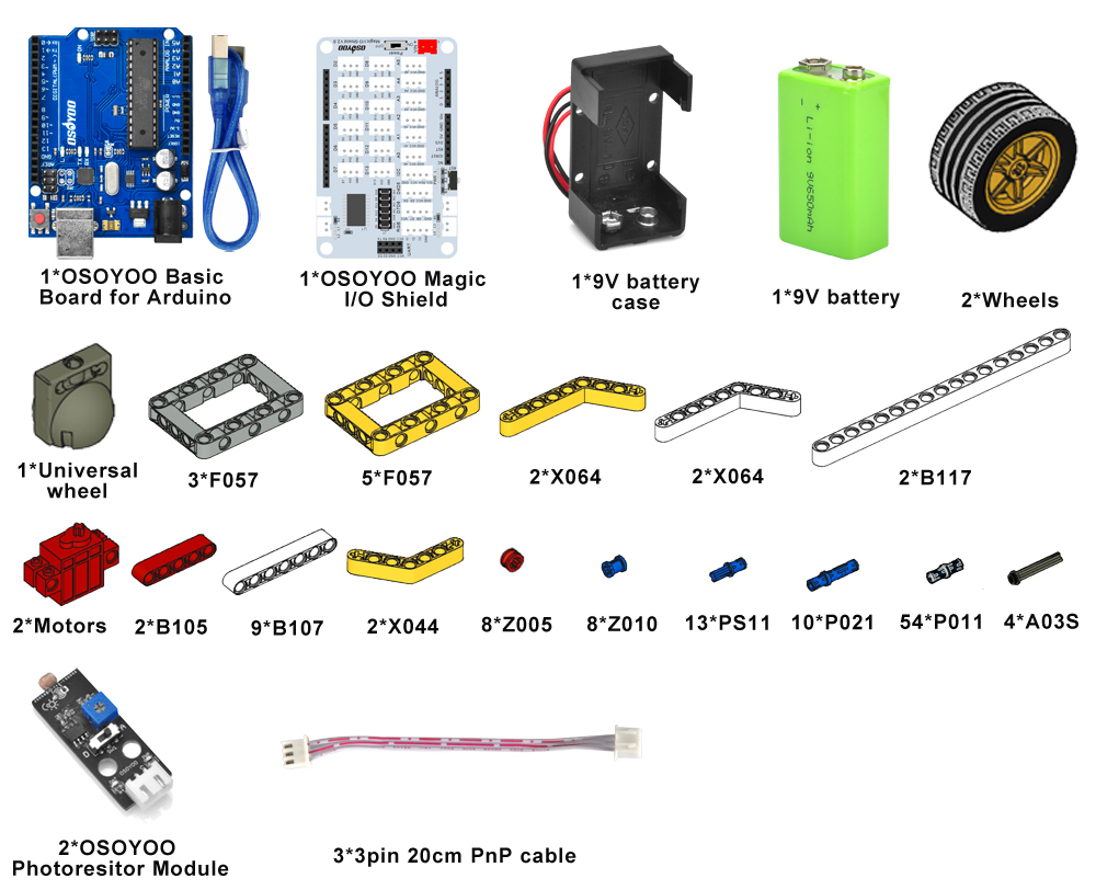
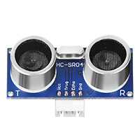
Please prepare the following parts to complete this project NOTE:
1.the color of the building block is subject to the actual product, which does not affect the use.
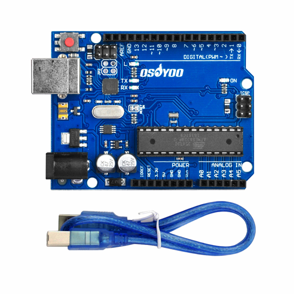
2. ALL OSOYOO PRODUCTS FOR ARDUINO ARE THIRD PARTY BOARD WHICH IS FULLY COMPATIBLE WITH ARDUINO
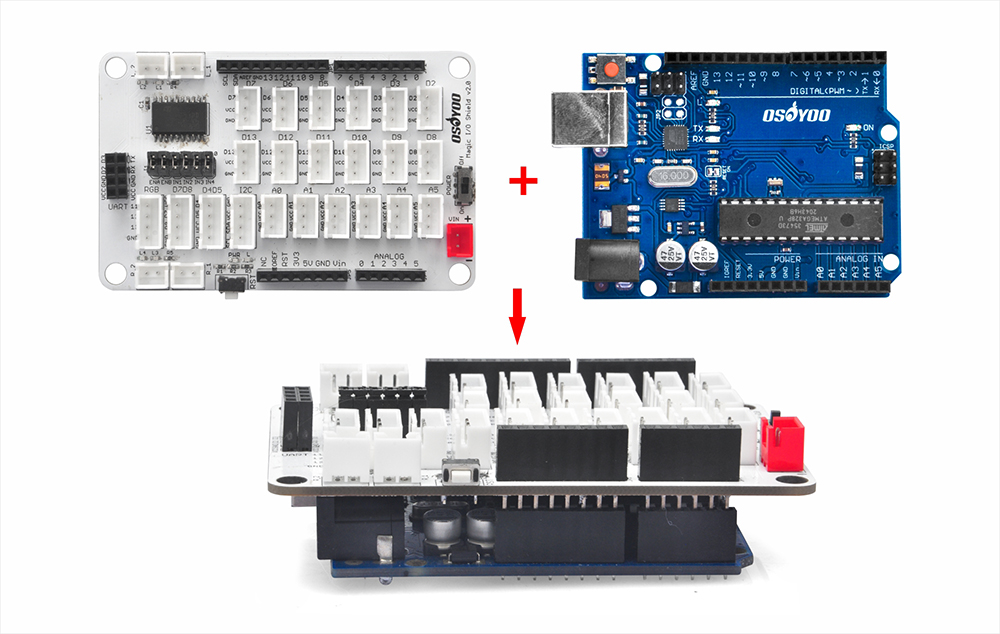
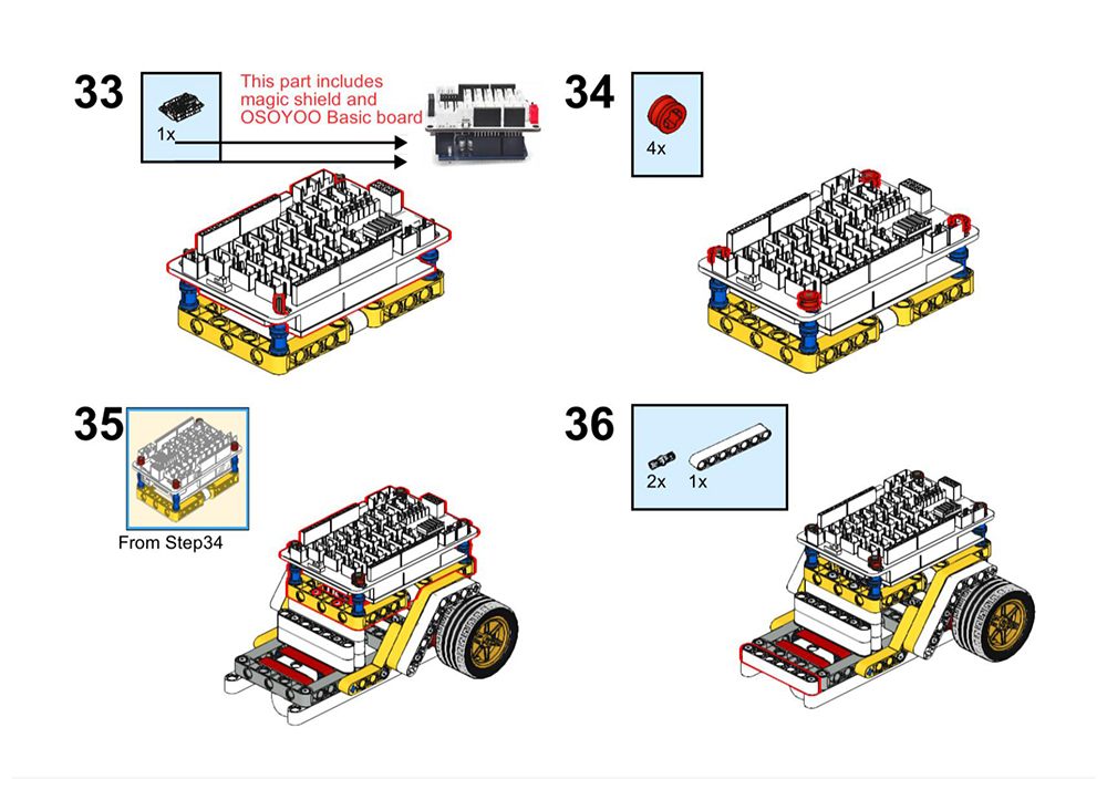
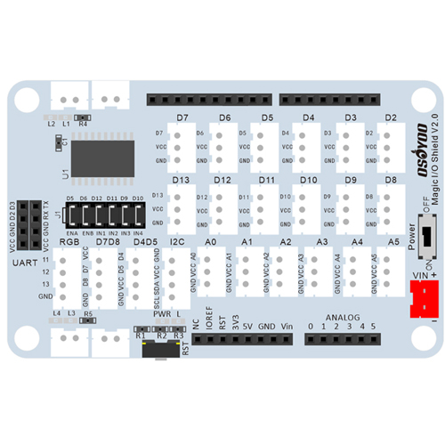
Before you build the robot with blocks, please install OSOYOO basic board for Arduino under OSOYOO Magic I/O shield as following (Attention please : the pins of I/O shield is aligned with the port of basic the board firstly, then press the shield tightly on the board).
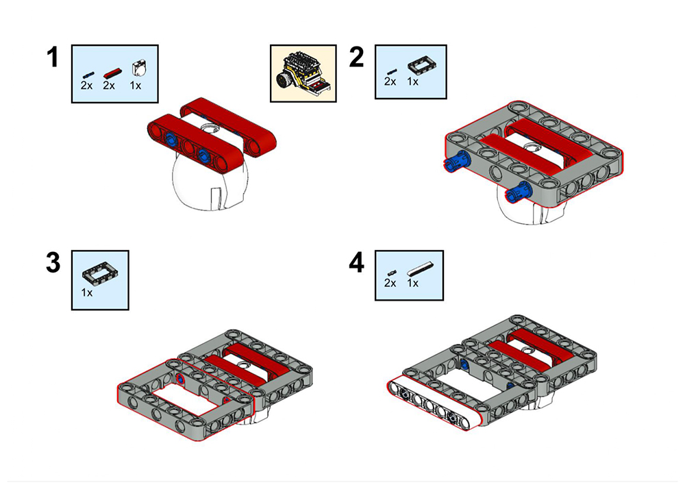
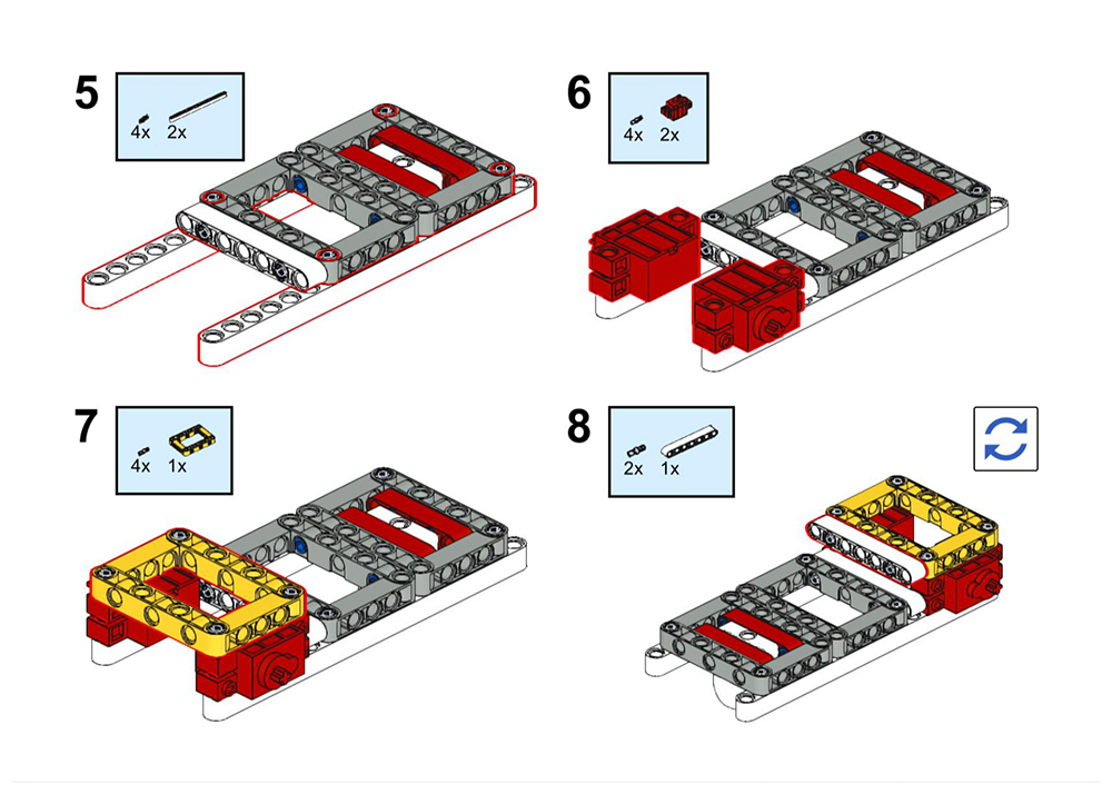
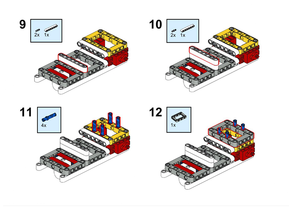
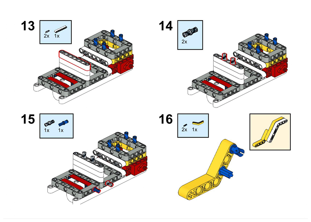
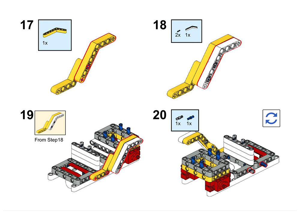
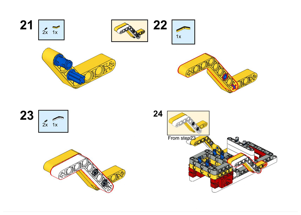
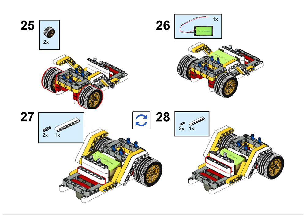
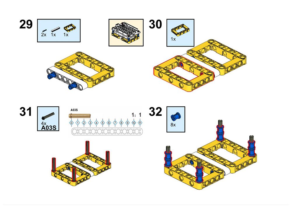
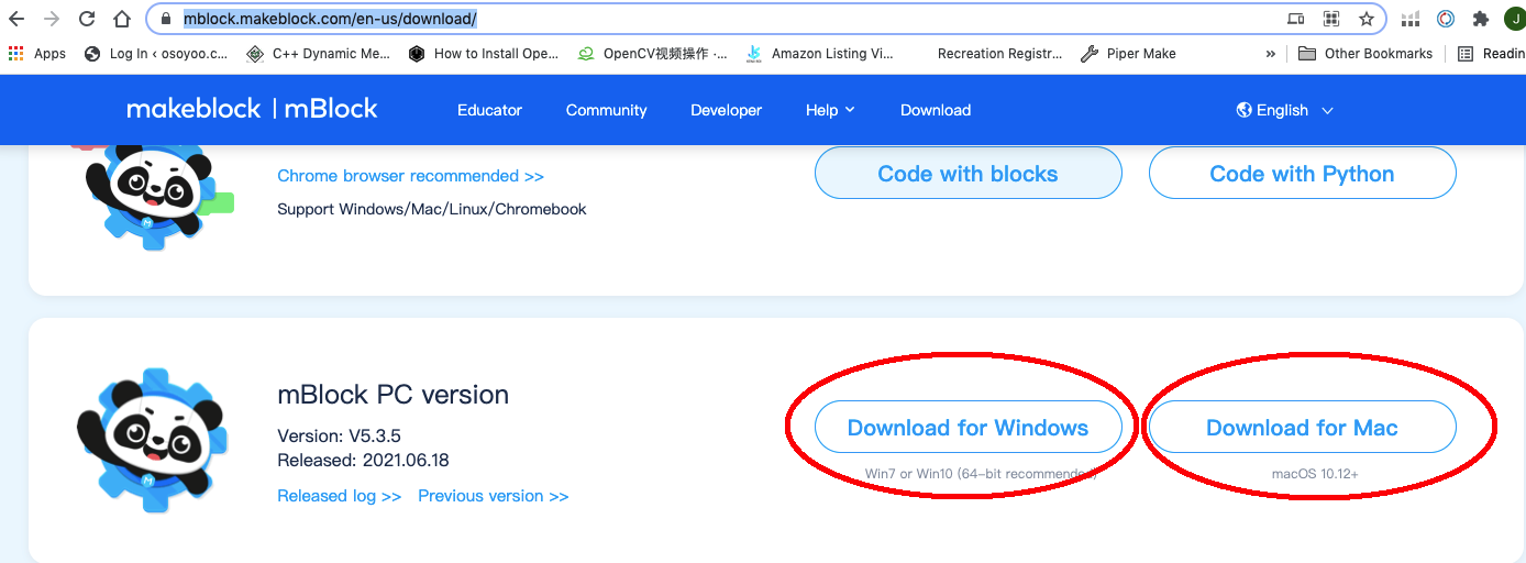
Please follow the building steps to build this robot car, If you want to get clear PDF building steps, please download from https://osoyoo.com/picture/Building_Robot_Car/lesson3/LESSON3.pdf
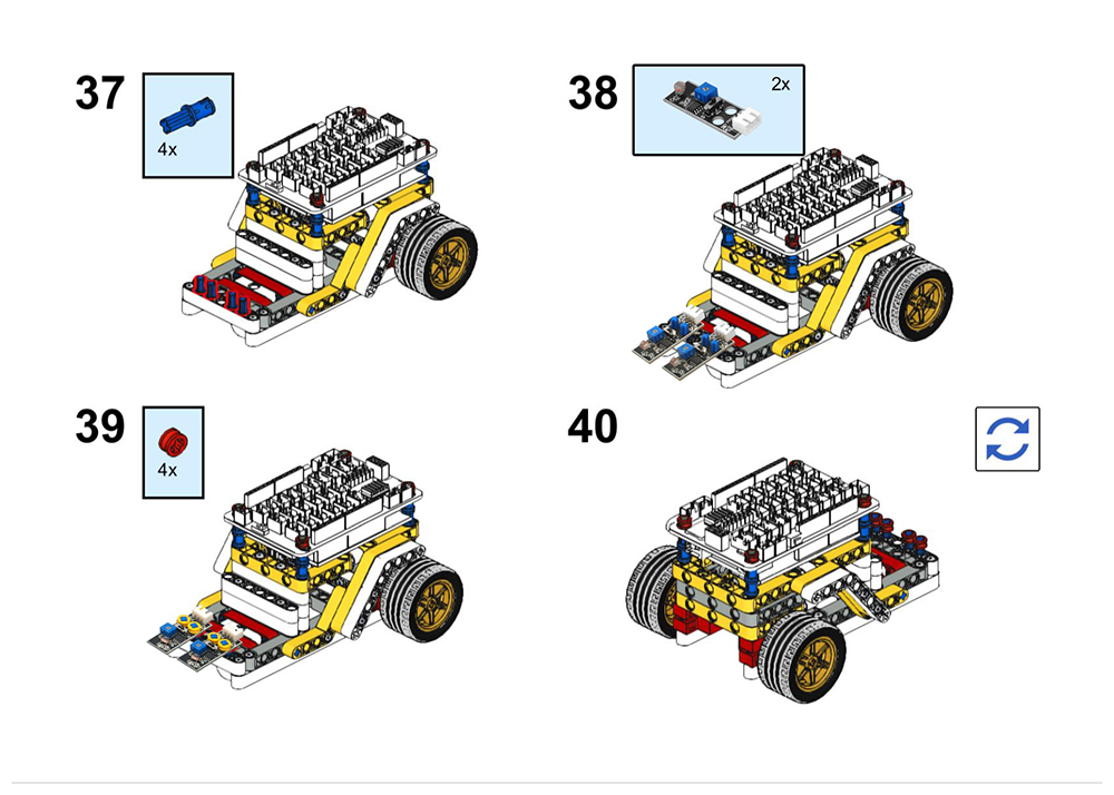
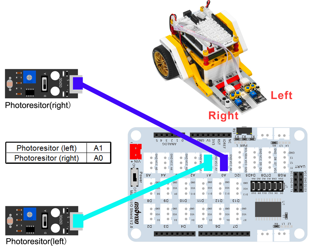
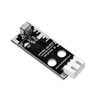
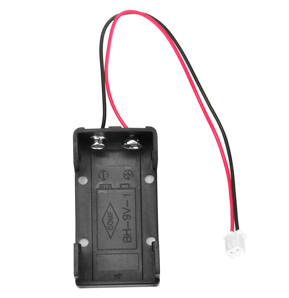
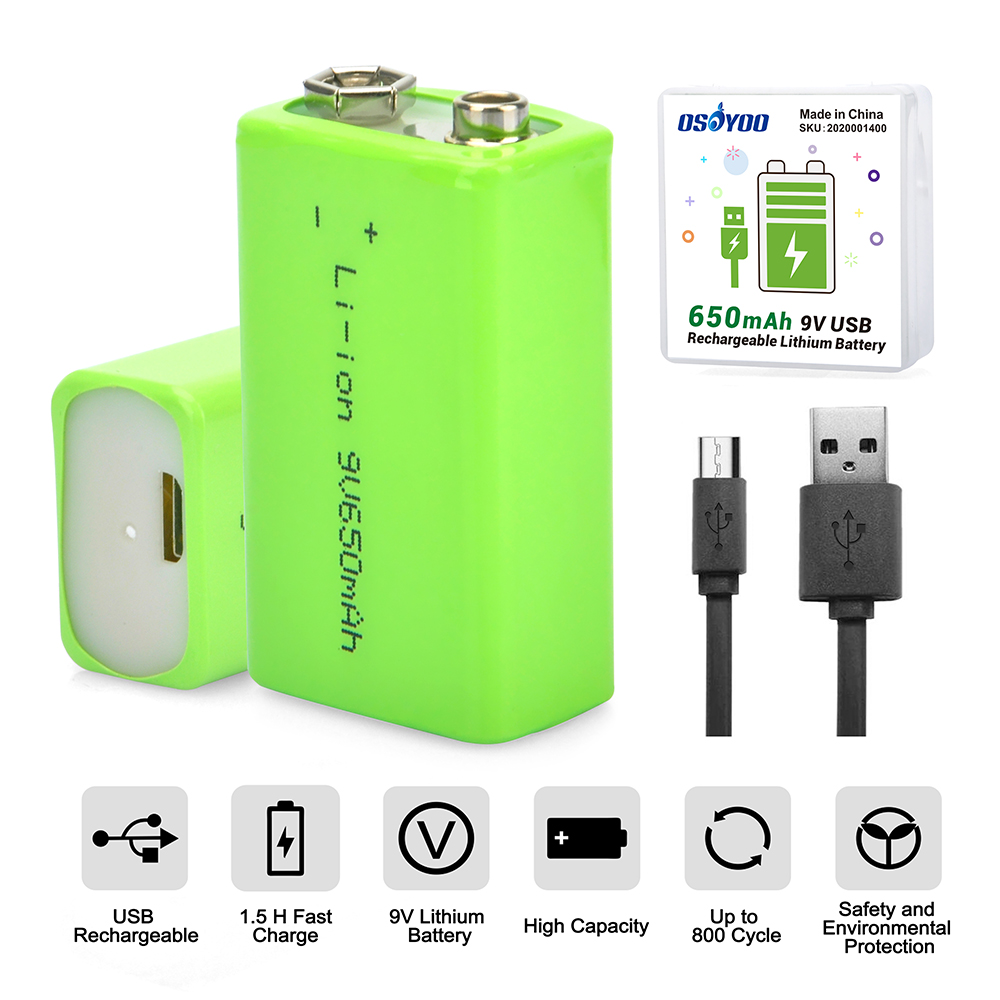
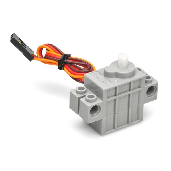
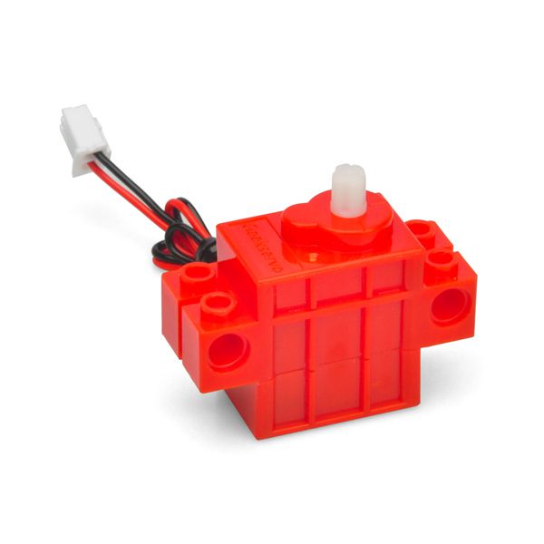
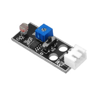
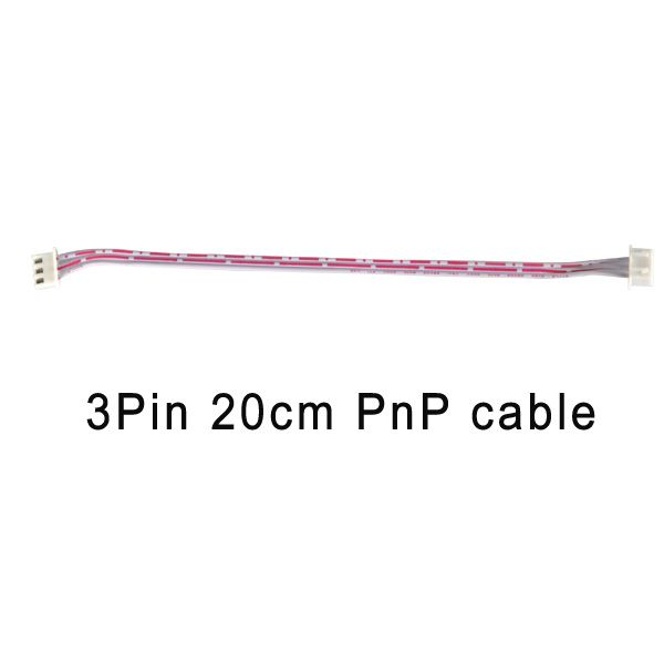
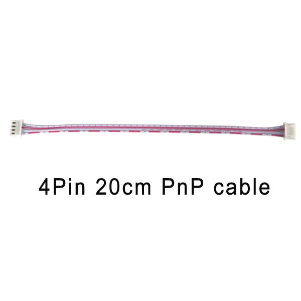
Please connect motors and 9V battery case as lesson1.Then connect left photoresistor to A1 of the Magic I/O shiel, right to A0 port with 3-pin PNP cables as below (Attention please: there are six jumper caps on ENA/ENB/IN1/IN2/IN3/IN4):
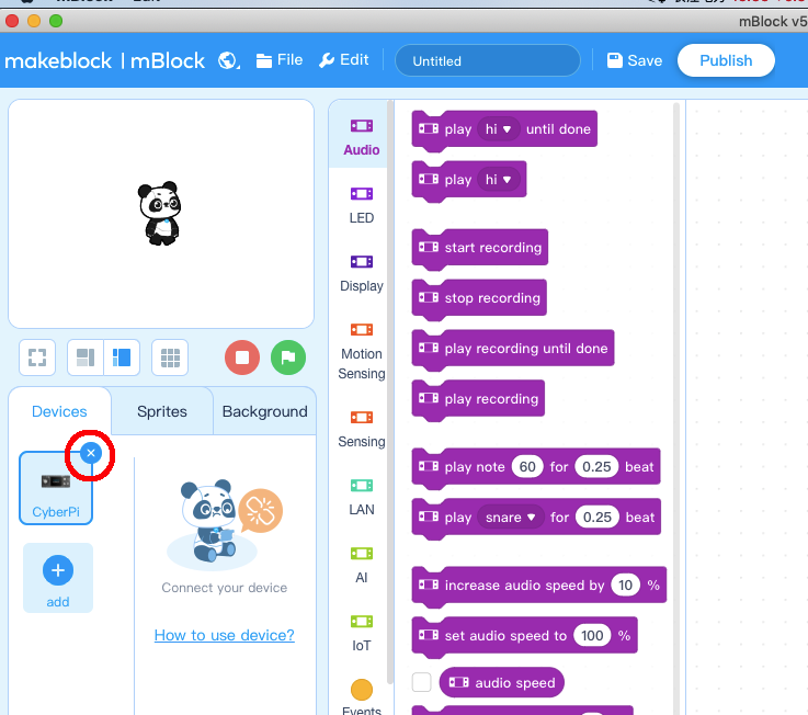
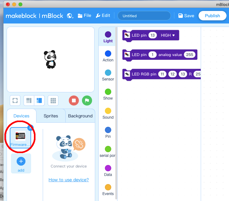
Step 3) Run the mBlock PC software by double click the lovely Panda icon. you will see mBlock UI as following picture. Please delete the default device CyberPi by click the cross in the red circle.
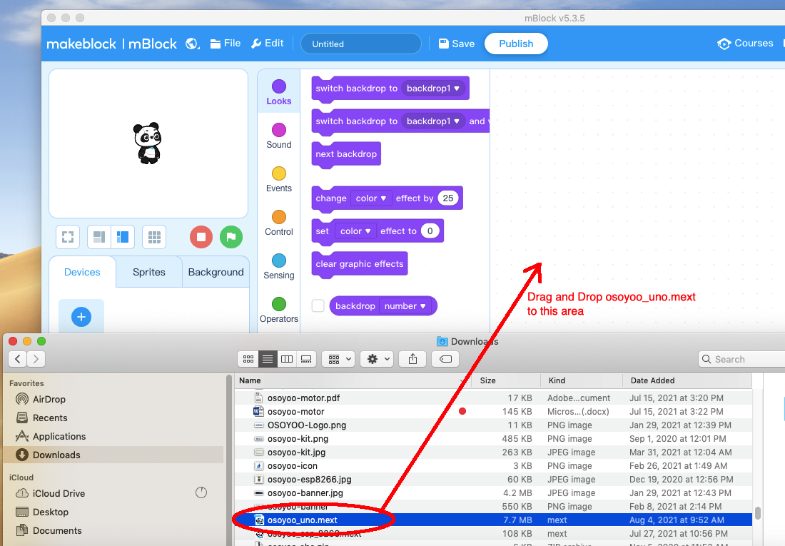
Step 4) Drag and Drop osoyoo_uno_mext file(downloaded in Step 2) to mBlock software as following:
Now you will see a new device firmware in mBlock, see following picture:
Now mBlock software and OSOYOO_UNO device firmware have been successfully installed in our PC!
Now we will show you how to use blocks to turn above idea into reality.
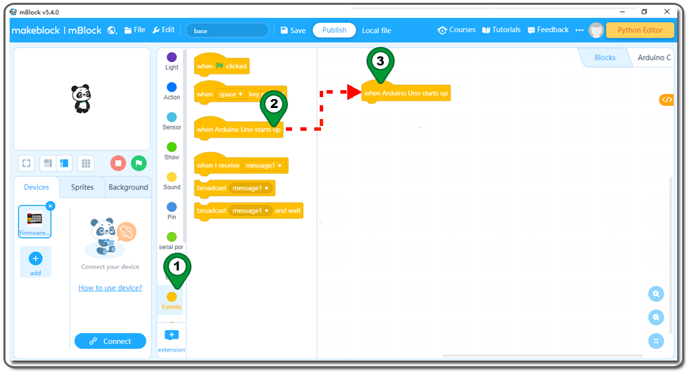
Step 5)Click Events, add when Arduino Uno starts upblock to the top:
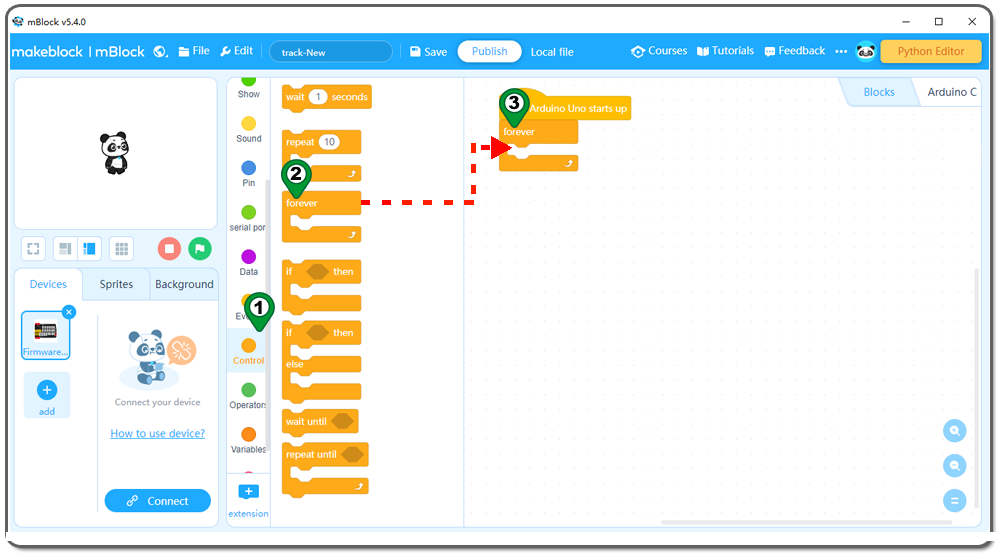
Step 6: Click Control, then Drag and drop Forever block to programming area as following:
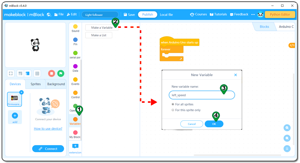
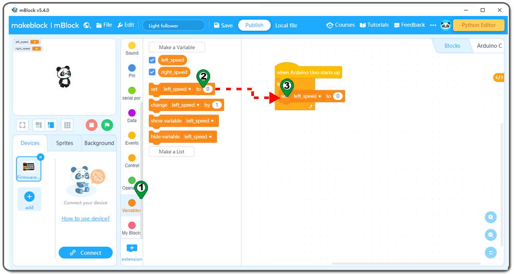
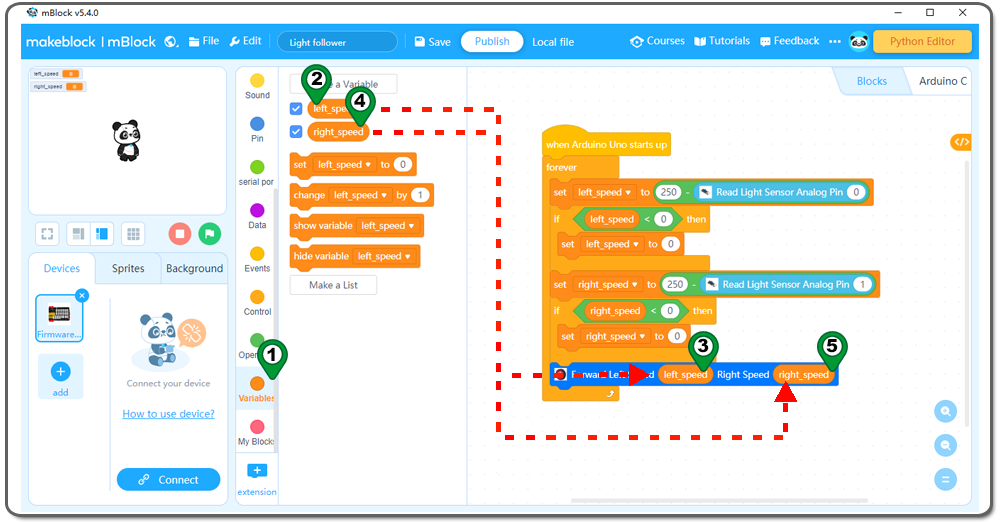
Step7: Click Variable , then click Make a Variable ,A new dialog will pop up,write left_speed ,than click OK,you will have a new variable left_speed ;Use the same method to create a right_speed variable;
Step 8: Click Variable again, then Drag and drop set left_speed to block to programming area as following:
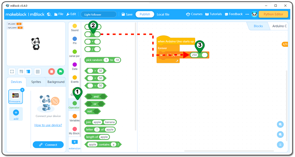
Step 9:Click Operation , then Drag and drop 0-0 block to programming area ,write 250 to the first area as following;
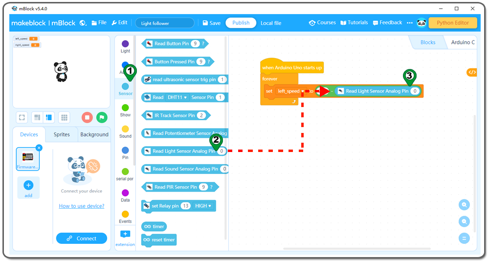
Step 10: Click Sensor , then Drag and drop Read Light Sensor Analog Pin block to programming area as following;
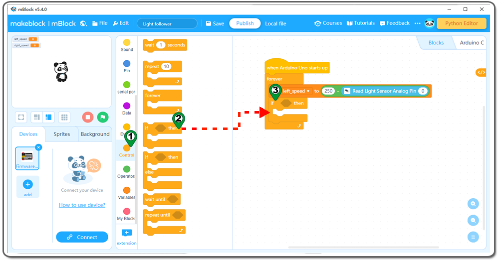
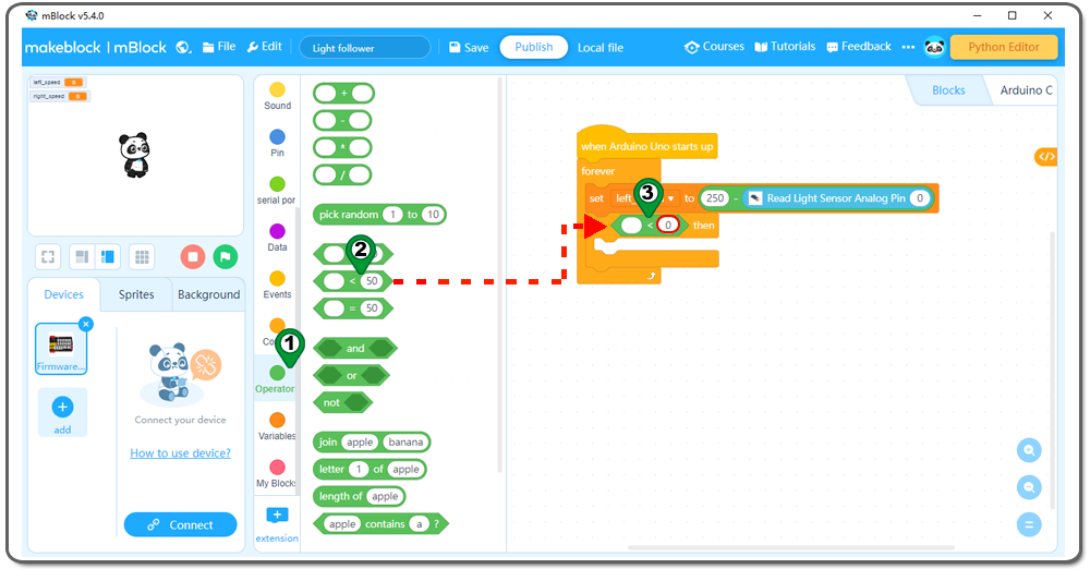
Step 11:Click Control, add anif then block inside forever loop as following :
Step 12: Click Operation , then Drag and drop 0<0 block to programming area ,write 0 to the second area as following;
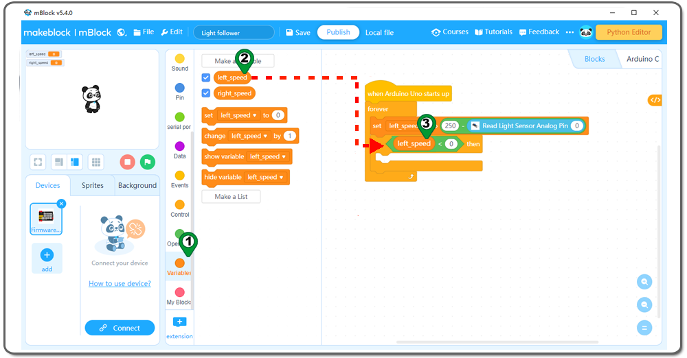
Step 13: Click Variable , then Drag and drop left_speed block to programming area as following:
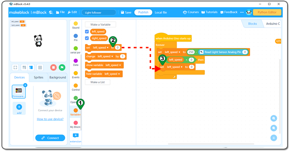
Step 14: Click Variable again, then Drag and drop set left_speed to block to programming area as following:
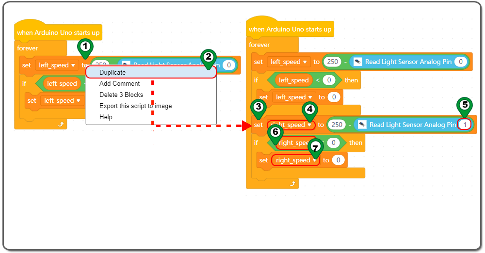
Step 15: Right Click set left_speed to block , then Drag and drop these block behind if then block ,change the left_speed to right_speed as following:
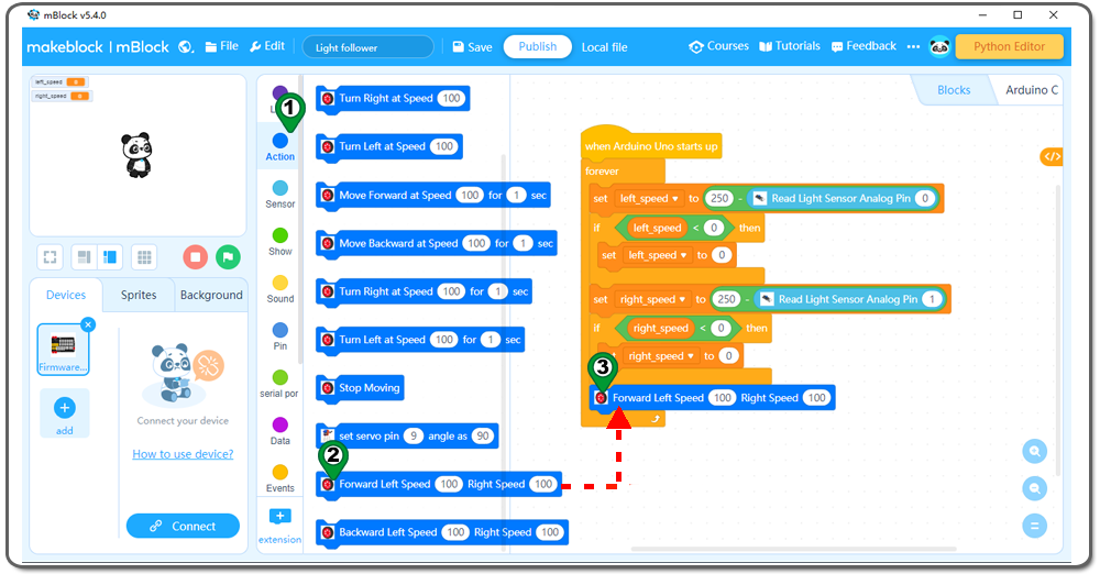
Step 16:Click Action again, then Drag and drop Forward Left Speed 100 Right Speed 100 block to programming area as following:
Step 17:Click Variable , then left_speed block and right_speed block to programming area as following:
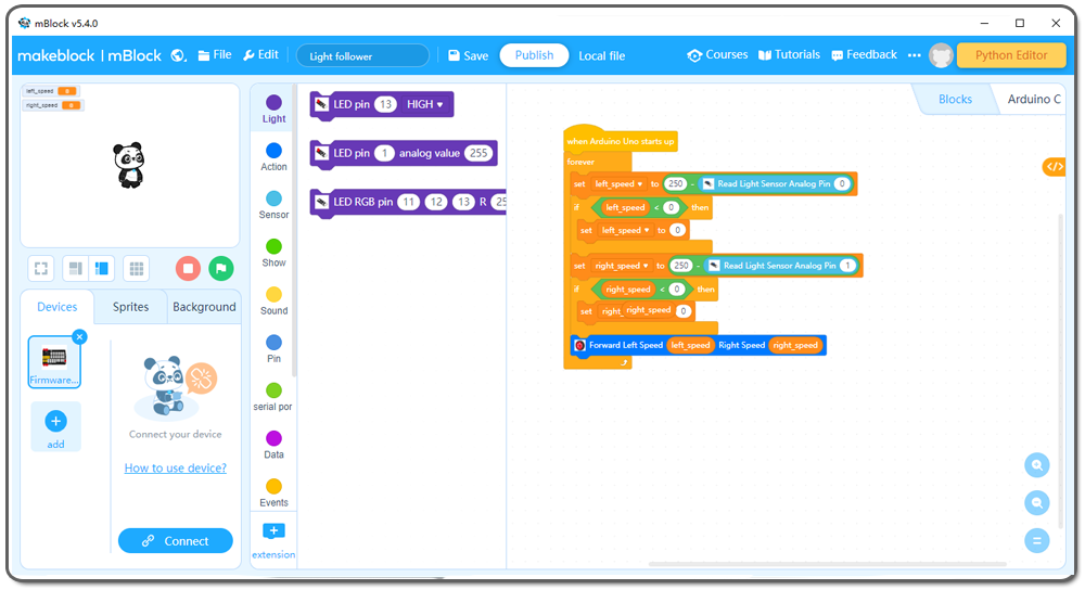
Now we have completed the block programming. The final blocks look like following:
Now all the programming blocks have been completed! From above picture, the logic is pretty straight forward:
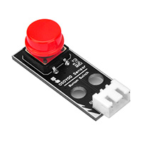
When Arduino is started, computer will enter a dead loop which will check the button status, when button is not pressed, the servo will stop at original position (in my servo 0 degree ) and elevator is in the ground , when button is pressed, the servo arm will rotate from 0 degree position to 180 degree position and the elevator is lifted to the air.
Step 18) Upload the program to OSOYOO basic board
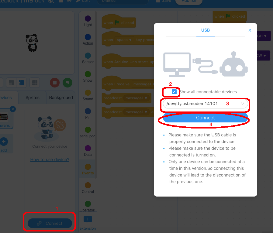
1) Please connect your OSOYOO basic board to your PC with USB cable firstly. Then click the Connect button in the bottom of the mBlock software, you will see a USB window pop up,
2) select Show all connectable device check box , then a device drop-down menu will show up,
3) select your port from device drop-down menu
4) click Connect button to connect your PC to OSOYOO basic board.
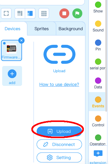
5)After you PC is connected toOSOYOO basic board, please click Upload button in the bottom of your software, then the code will be uploaded to OSOYOO basic board:
In previous Lesson 1 and Lesson 2, we have learned some basic control and action program blocks. In this lesson, we will learn some new program blocks: i)Read Light Sensor from Analog Pin Block from Sensor category
This block is an oval shape block which means it returns numeric value between 0 to 255. The number zero in the right side means the sensor will read light value from A0 pin(left light sensor).
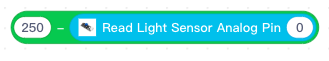
ii)Minus calculation block from Operator category
Above block calculates the result of 250 minus the value from A0 sensor .
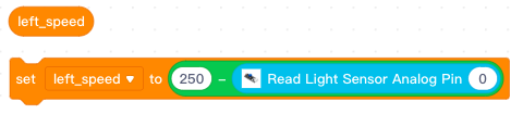
iii)Variable Block and Set Variable to Block in Variable Category:
Variable Block is often defined to save a calculation result for later use.
Above block defined a variable block “left_speed”, then set its value to the calculation of 250 minus A0 light sensor return value. The light value is higher, the left_speed is smaller, so the car will make left turn.
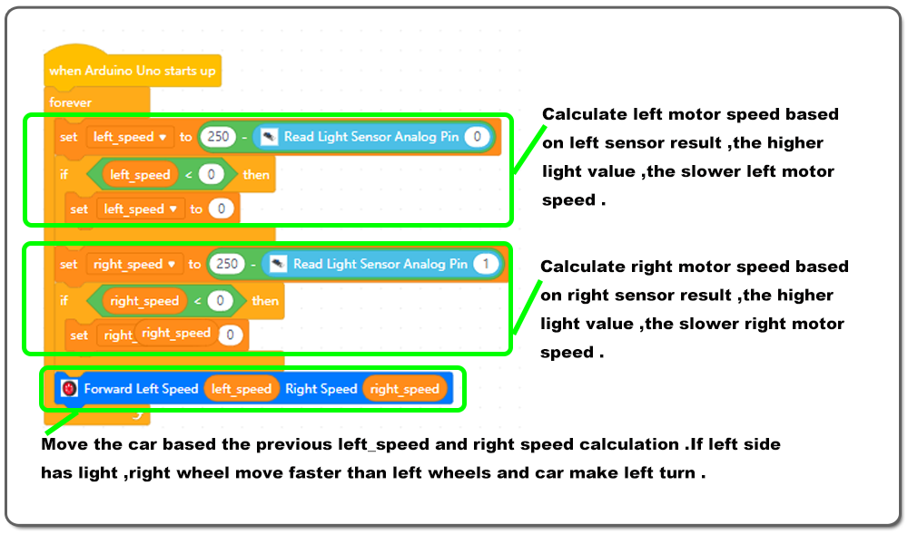
Here is full program block explanation:
The working principle of Photoresistor is that the stronger light of the Photoresistor detecting, the lower value of Photoresistor reading. The value of the Photoresistor reading are more than 0.
In the program we set left motor speed as a variable of left_speed, right motor speed as a variable of right_speed. Speed motor is between 0-255.
The variable of left_speed equals to 250 minus the value of left Photoresistor(A0) reading, and the variable of right_speed equals to 250 minus the value of right Photoresistor(A1) reading. If the variables are less than 0, the program sets these variables equal to 0。
If the value of left sensor(A0) reading is less than 250, left motor will move forward;
If the value of left sensor(A0) reading is more than 250, left motor will stop;
If the value of right sensor(A1) reading is less than 250, right motor will move forward;
If the value of right sensor(A1) reading is more than 250, right motor will stop;
If the value of both sensor reading are less than 250, both motors move forward.
Upload followlight.ino sketch code to Arduino. Turn on the car.
Illuminate the front photoresistor sensor with a flashlight. Then the car will follow the flashlight to make movement.
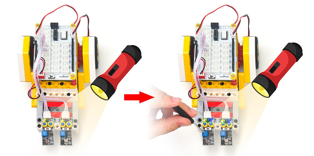
If the torch shines on the photoresistor sensor, but the car does not move. Please adjust the adjuster as shown in the picture. Under normal circumstances, the yellow light and the blue light will be on at the same time when the torch is illuminated.