Buy from US Buy from UK Buy from DE Buy from FR Buy from IT Buy from ES ここでご購入を!

Introduction

In this lesson, we will show how to use the OSOYOO IoT Kit to build an RFID access control system. Before starting this lesson, you can get more information about the RFID module from this link.

HARDWARE

SOFTWARE

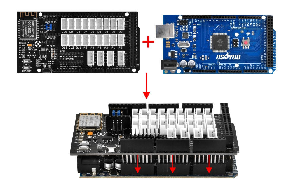
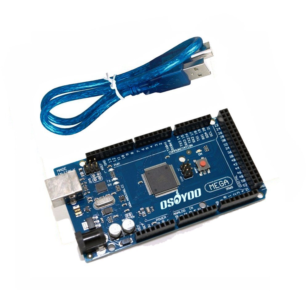
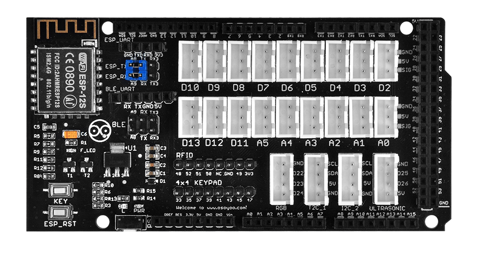
First, plug the OSOYOO MEGA-IoT Extension Board into the MEGA2560 board:

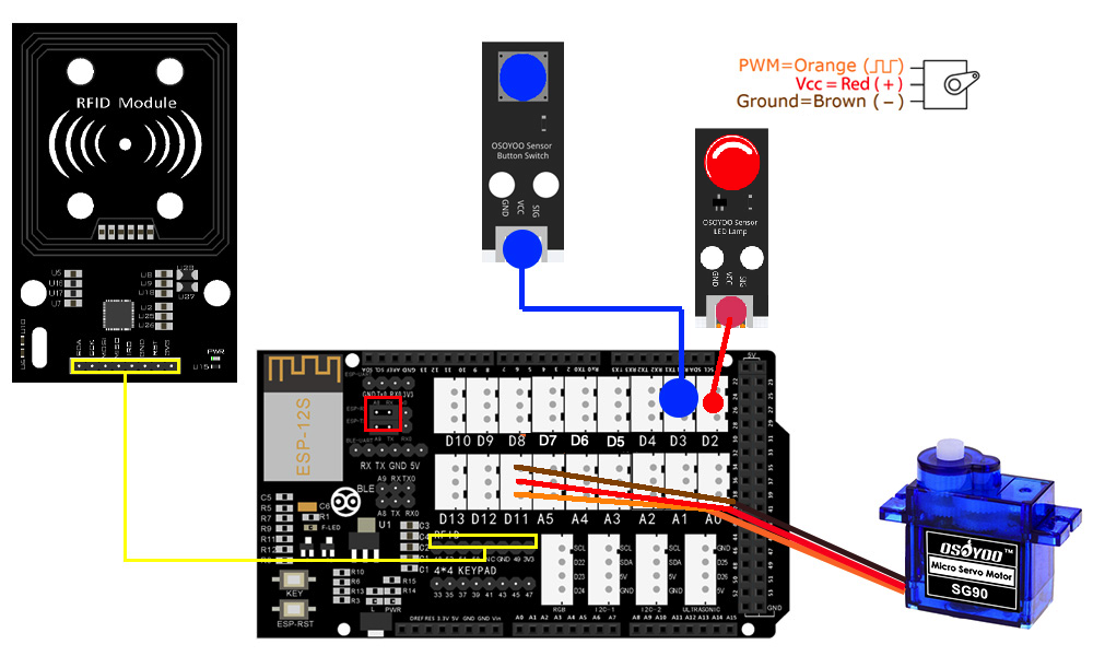
Build the circuit as shown below:

RFID Module – RFID Port
Push Button – D3 port
LED Module – D2
Door Servo – D11

Check that the wiring is correct by verifying the VCC and GND pin labels.

Prerequisite:
If you haven’t installed the WifiESP, I2C LCD, and PWMServo libraries in previous lessons, please download them from the following links:

This lesson also requires the RFID library. If you don’t have it, download it from the following link:

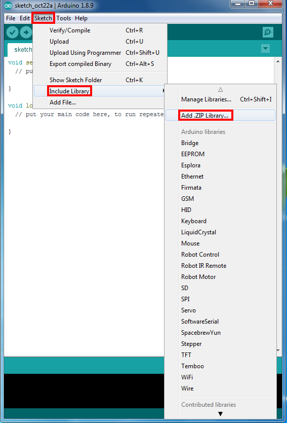
In Arduino IDE, click Sketch > Include Library > Add .ZIP Library and add each library zip file.

Servo Test

Step i) Before uploading the code, adjust the servo angle first. Remove any items from the wooden house’s door area:

Then download the servo test code from this link and unzip it:

https://osoyoo.com/driver/smart-home-v2-udp/lesson5/servo_config.zip

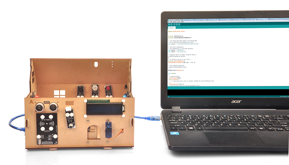
Step ii) After completing the above operations, connect the OSOYOO MEGA2560 Board to your PC with a USB cable.

Notice: Turn off your battery or unplug your power adapter before uploading a sketch to the Arduino.

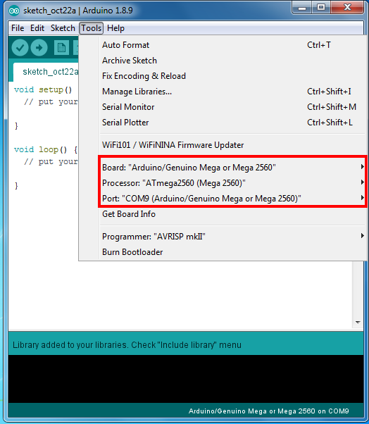
Step iii) In Arduino IDE, choose the correct board type and port for your project.

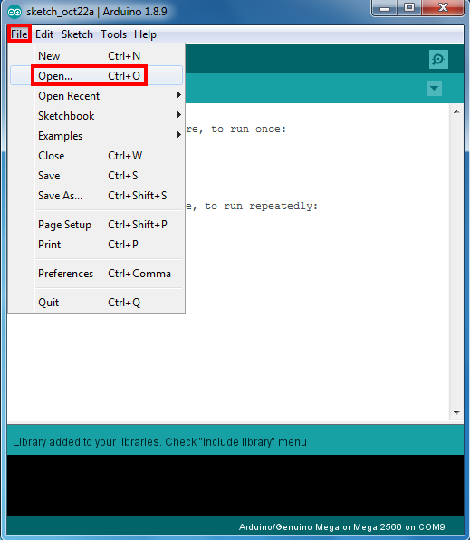
Step iv) In Arduino IDE, click File > Open, choose the code in the folder, and load the servo_config.ino sketch onto your Arduino.

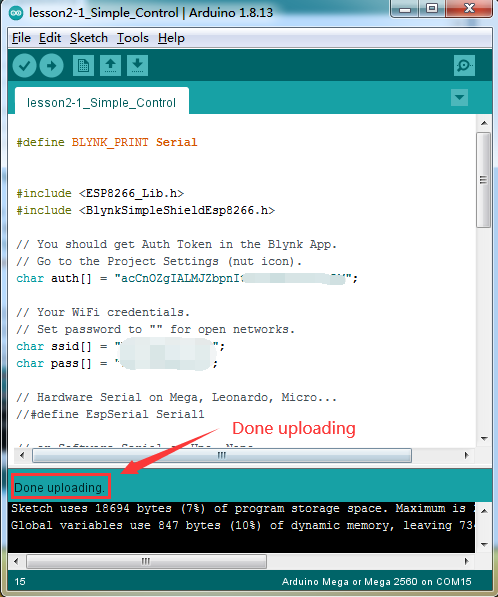
Upload the sketch to the board. Wait until you see:

Done uploading

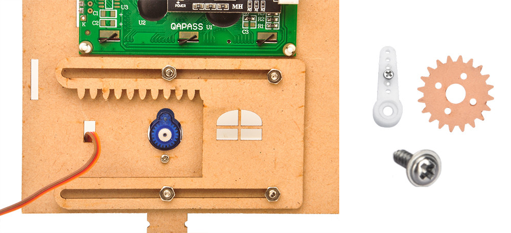
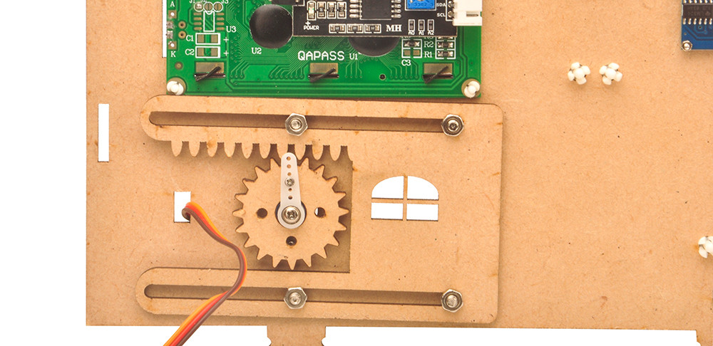
Step v) After uploading the code, the servo will turn to the 0-degree position. Now install the wooden gear and the white fixed arm:

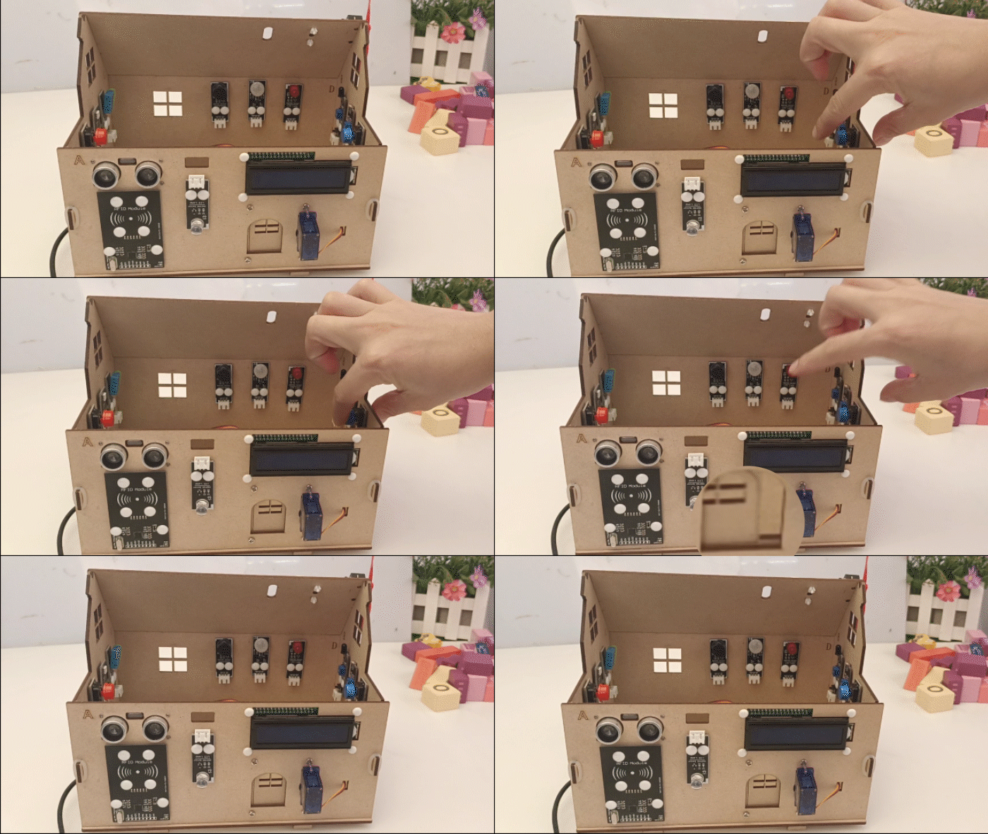
Step vi) Press the button to simulate opening the door; release it to simulate closing the door.

After the servo test and installation are complete, you can move on to the next task. If the door does not open or close properly, adjust the servo arm starting position accordingly.

Download and Edit the Lesson 2-5 Arduino Code:
Step 1: Download the code from the following link:
https://osoyoo.com/driver/smart-home-v2-udp/lesson5/smarthome2-5.zip

Unzip the file and double-click smarthome2-5.ino to open it in Arduino IDE.

Step 2: Find the following lines and replace *** with your Wi-Fi SSID and password:

char ssid[] = "***";//replace this line with your wifi ssid
char pass[] = "***"; //replace this line with your wifi password

Replace *** with your correct Wi-Fi SSID and password; otherwise your project cannot connect to the internet.

Step 3: Upload the sketch to the board. Wait until you see:

Done uploading

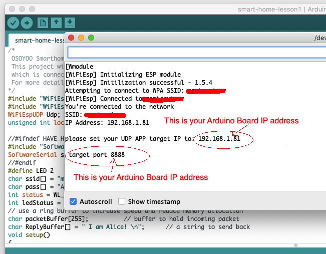
Now open the Serial Monitor. You will see your Arduino’s IP address:

In the example above, 192.168.1.81 is the IP address of the Arduino. You will need to enter this IP address in the app later.

**********************************************************

Add Your Own RFID Card ID:

After completing the above steps and uploading the code, open the Arduino IDE Serial Monitor to find your RFID card number.
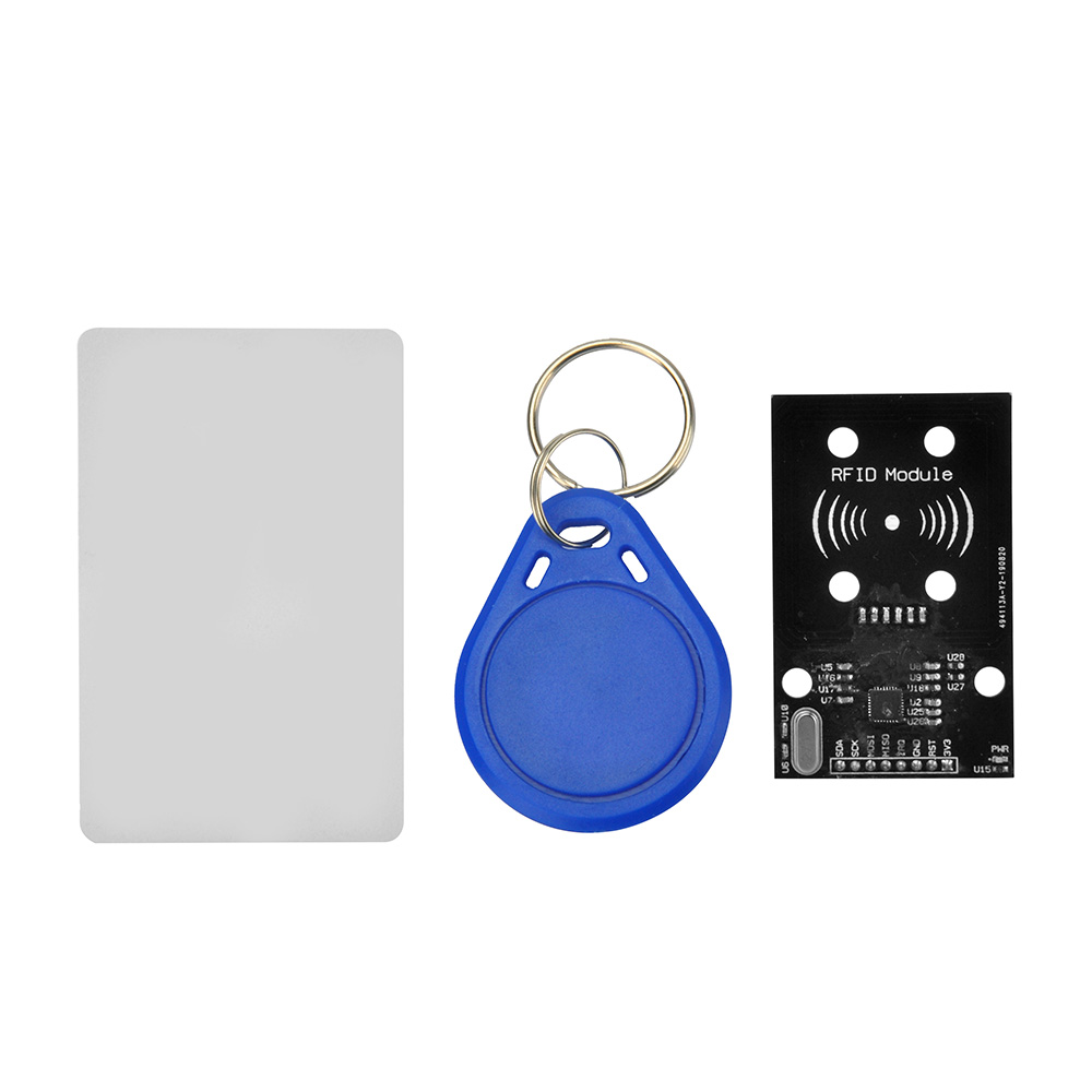
To do this, take a white or blue RFID card and tap it against the RFID sensor. You will see something like this:

RFID START!
Find the card!
Card type: Unknown
The card's number is : 71ba2f2eca
71ba2f2eca ID is unknown.

In the example above, 71ba2f2eca is your RFID card number. Now in line 15 of the code, change the variable marystr from 33cd216fb to 71ba2f2eca:

String marystr="33cd216fb"; //change 33cd216fb with your test ID card

After the change, line 15 will look like this:

String marystr="71ba2f2eca";

You can add or change card information at any time. When done, re-upload the code to the Arduino to continue the experiment.

**********************************************************

Upload the sketch to the board again. Wait until you see:

Done uploading

Now you can use the test RFID card to test the security door. Before testing, open the app first:

APP Installation and Setup:
Step 1: If you haven’t installed the OSOYOO IoT Robot App, search for “OSOYOO IoT Robot Car” in Google Play or the Apple App Store.
See the following tutorial link for more information about installing the app:
https://osoyoo.com/2022/02/06/smart-house-iot-learning-kit-v2-0-lesson-1-wireless-lighting-control/#installapp

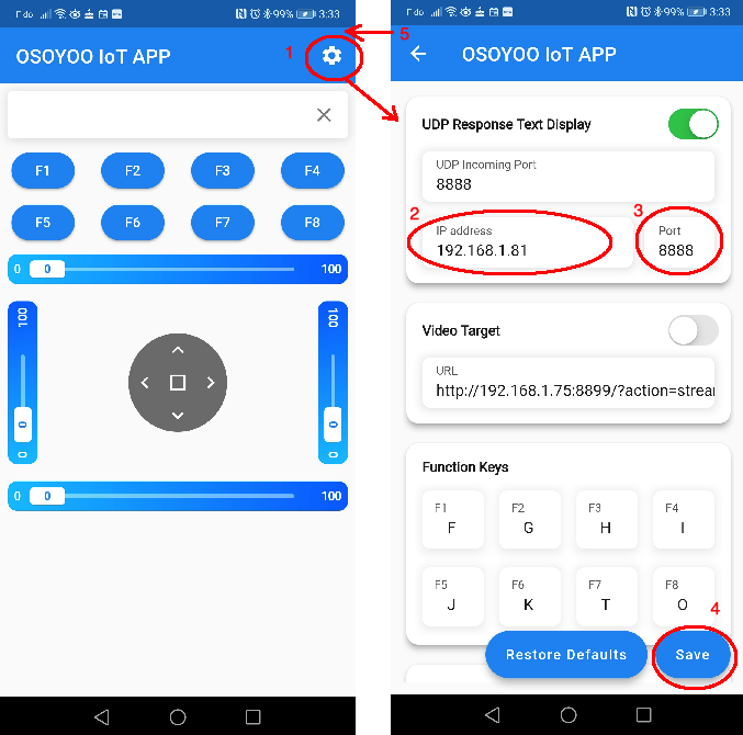
Step 2: Make sure your cell phone is on the same local network as the Arduino. Open the app, tap Settings, and enter the Arduino IP address from Step 3 above and set the Port to 8888:

Now tap the test RFID card against the RFID sensor. The door will open for 1 second and then close. The app will show “Mary at the Door.”

If you press the F8 key in the app, you can also open the door manually. The app will show “Door is open by APP.”

You can also push the button to open the door.

Each time the door opens, the LED turns on. When the door closes, the LED turns off.

No. Picture Device Qty. Link

1 OSOYOO MEGA2560 Board 1 Click here to buy
2 OSOYOO MEGA-IoT Extension Board 1 Click here to buy
3 Photosensitive Sensor 1 Click here to buy
4 Temp & Hum Sensor 1 Click here to buy
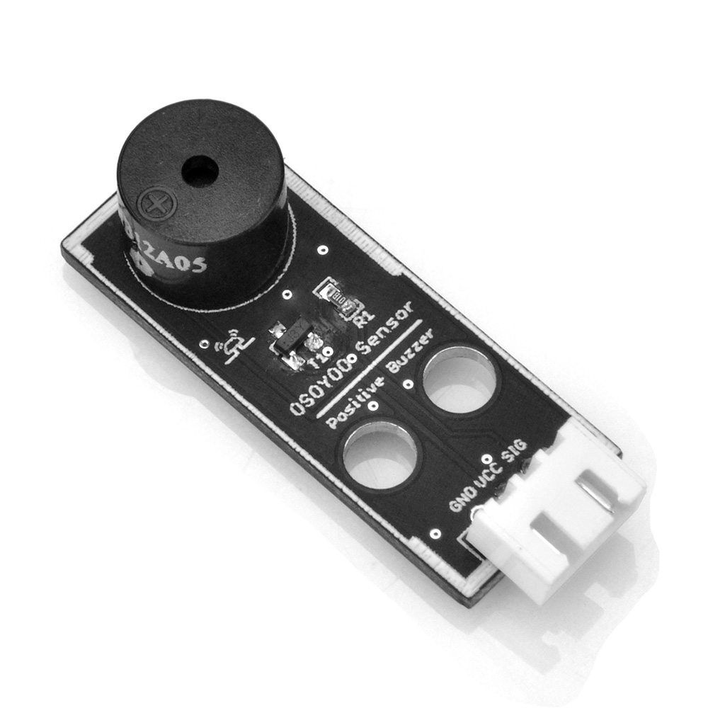
5 OSOYOO Active Buzzer Module 1 Click here to buy
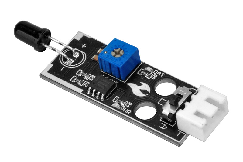
6 Flame Detection Sensor 1 Click here to buy
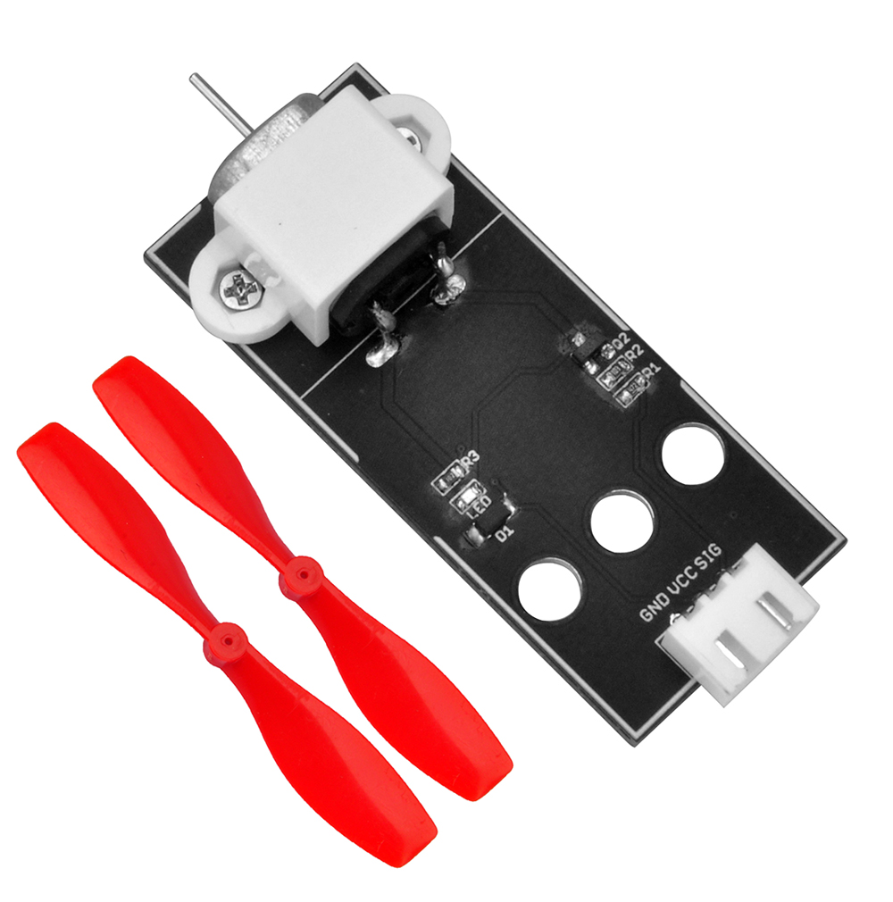
7 Fan Motor Module 1 Click here to buy
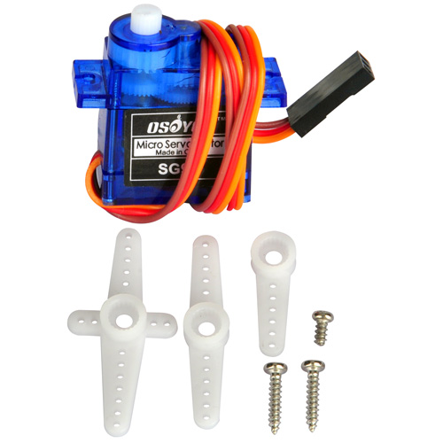
8 Micro Servo Motor 1 Click here to buy
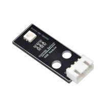
9 RGB Module 1 Click here to buy
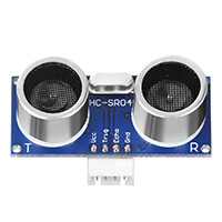
10 Ultrasonic Sensor 1 Click here to buy
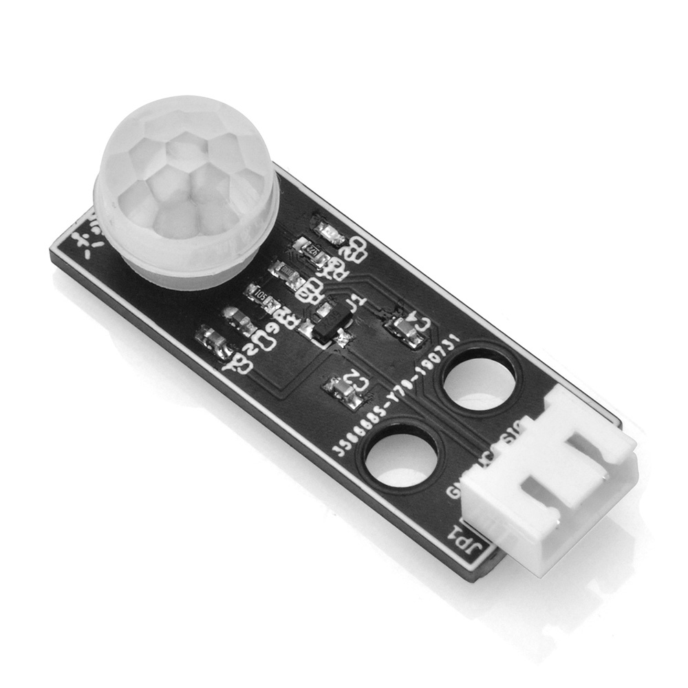
11 PIR Motion Sensor 1 Click here to buy
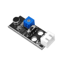
12 Microphone Module 1 Click here to buy
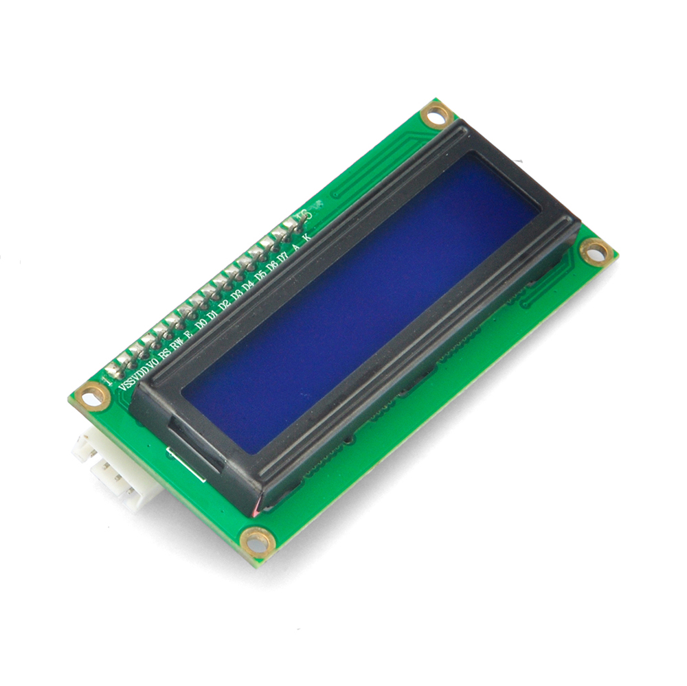
13 1602 I2C LCD Screen 1 Click here to buy
14 RFID Module 1 Click here to buy
15 White LED Module 1 Click here to buy
16 Red LED Module 1 Click here to buy
17 Colorful Light 1 Click here to buy
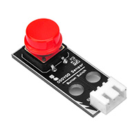
18 Red Button Module 1 Click here to buy
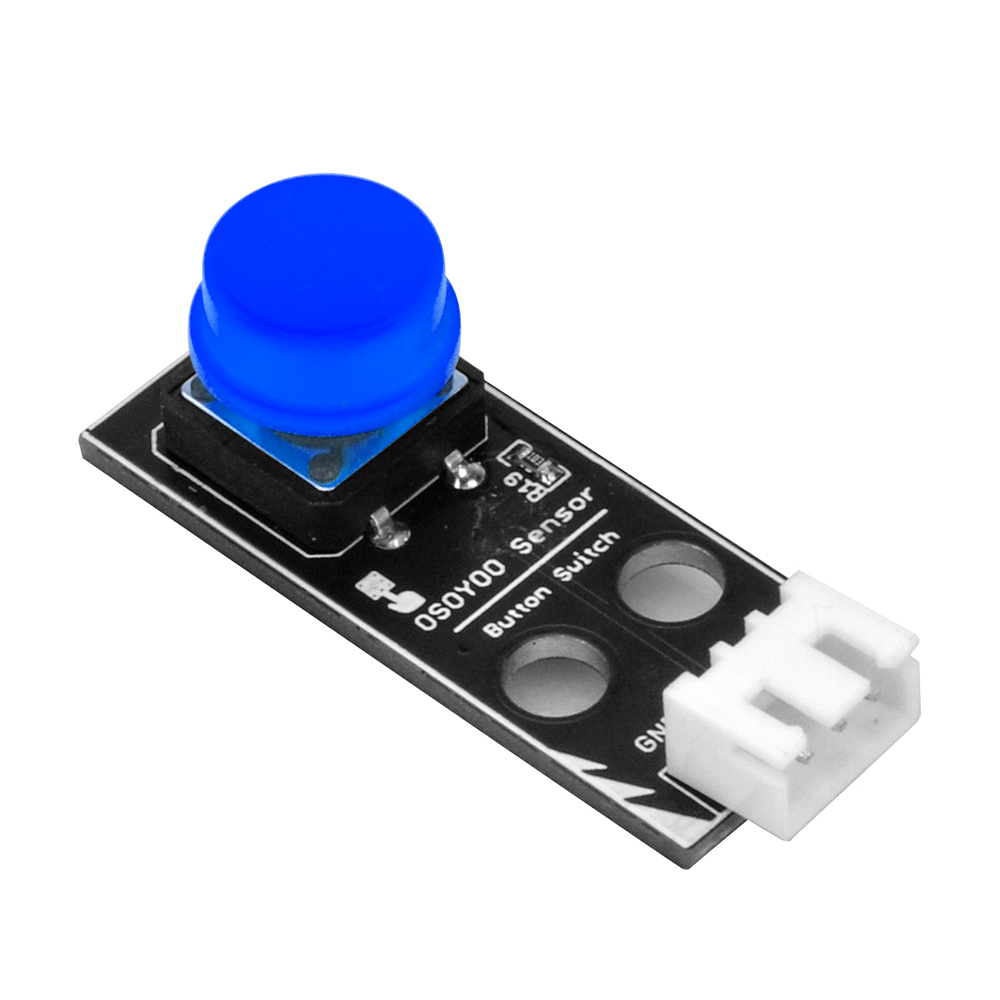
19 Blue Button Module 1 Click here to buy
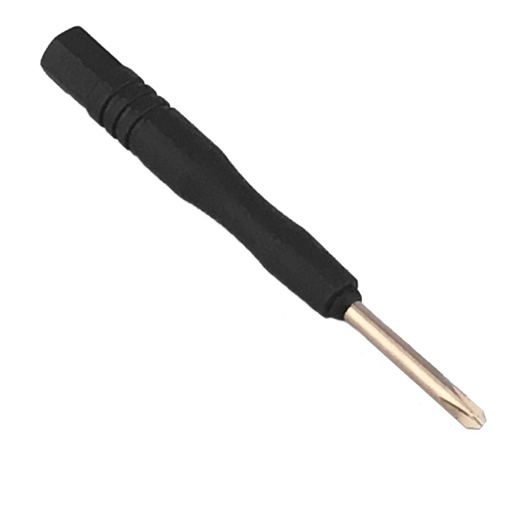
20 Philips Screwdriver 1 Click here to buy