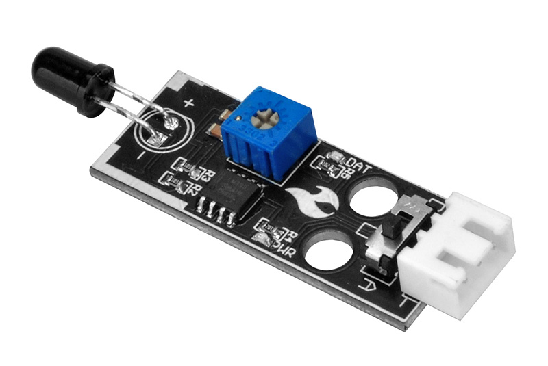
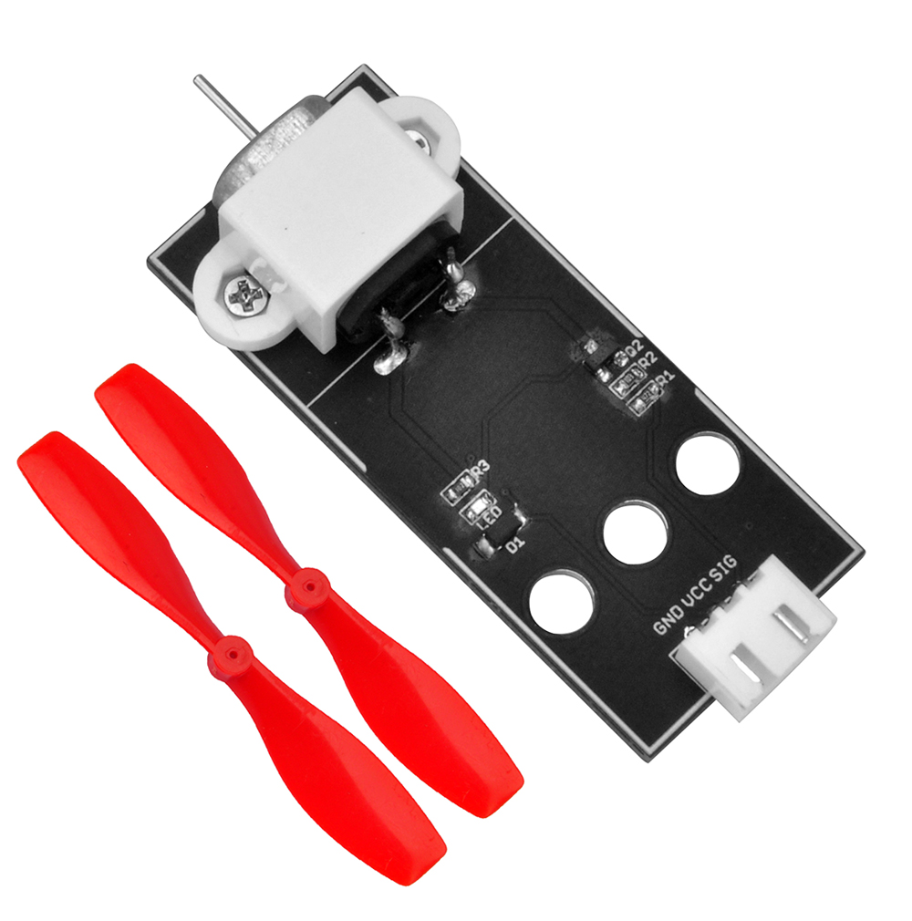
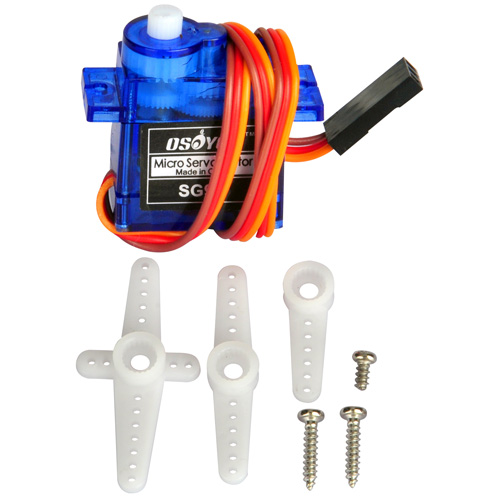
In this lesson, we will show how to use the OSOYOO Smart Home IoT Kit with the Blynk app to control electronic devices such as LEDs, active buzzers, fan modules, relay modules, and more.
We will learn how to use Blynk to remotely turn an LED on or off and control its brightness. Using the same principle, you can control other electronic devices as well.
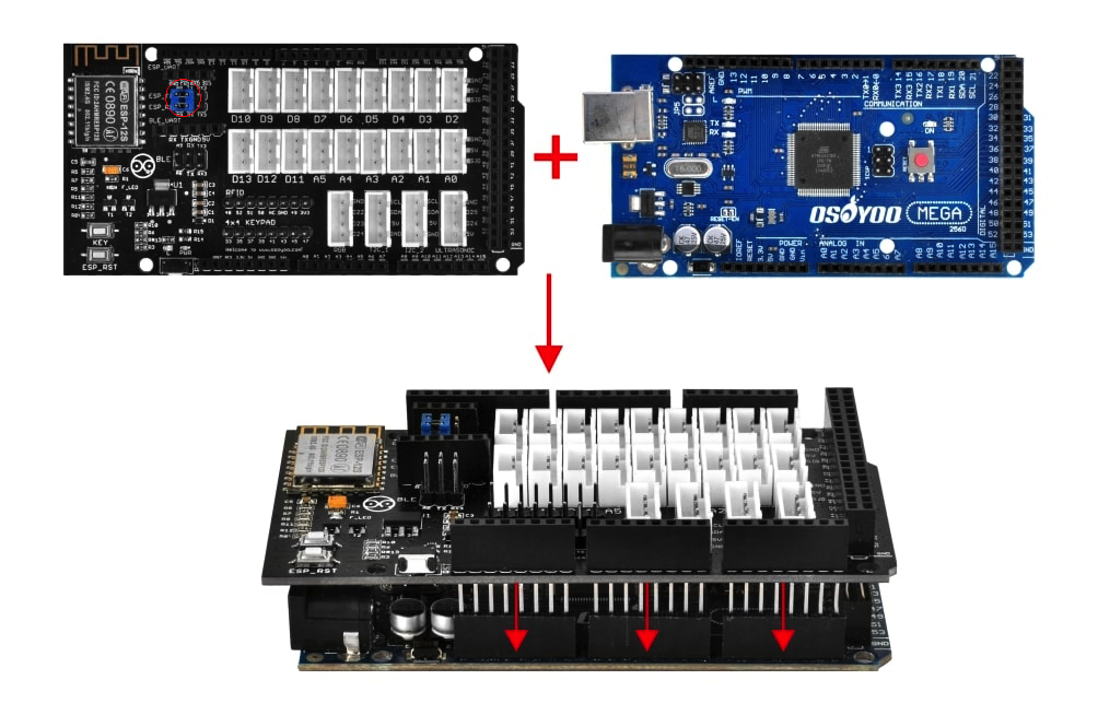
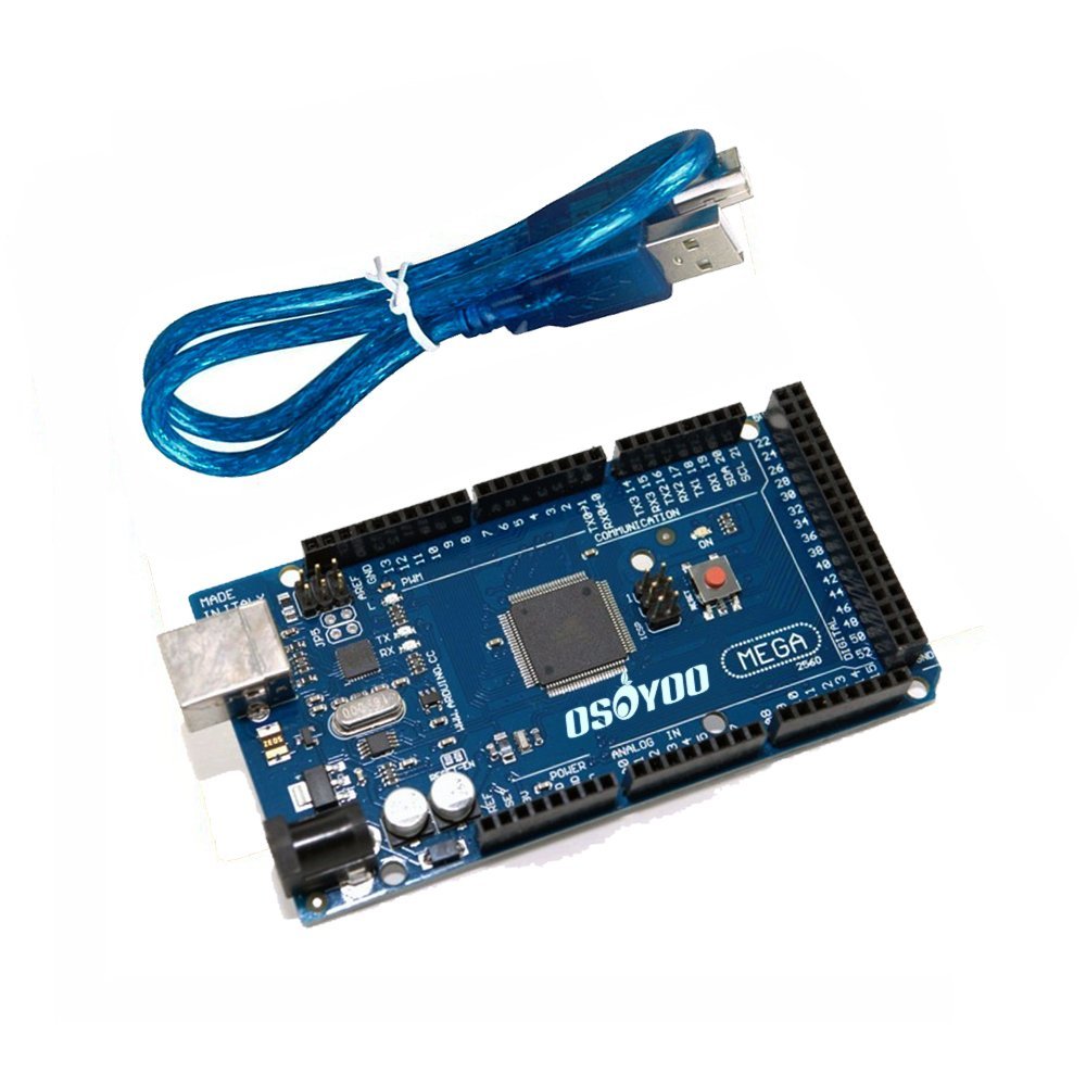
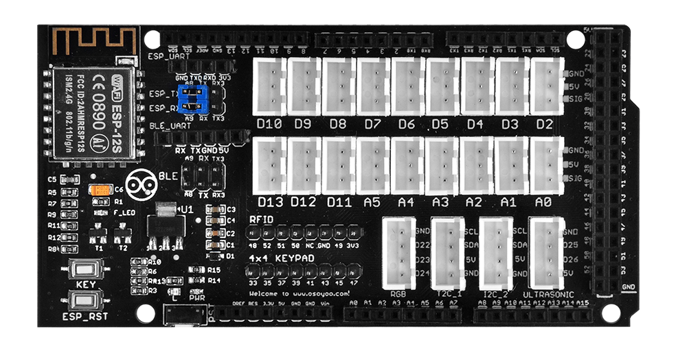
First, plug the OSOYOO MEGA-IoT Extension Board into the MEGA2560 board.
Make sure the jumper caps shown in the red circles below are installed. These two jumper caps connect A9 to ESP_TX and A8 to ESP_RX.
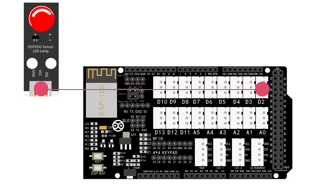
Connect the LED Module to the D2 port as shown below:
Prerequisite:
You must have installed the Blynk Legacy App on your Android device and set up a local Blynk server on a computer on your local network.
Google Play and the Apple App Store no longer support downloading the Blynk Legacy App. Android devices can still download the APK from this link: https://osoyoo.com/driver/blynk/blynk_legacy.apk
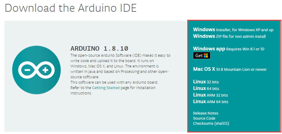
If you have not installed the latest Arduino IDE (if you already have version 1.1.16 or later, skip this step), download Arduino IDE from https://www.arduino.cc/en/software and install it.
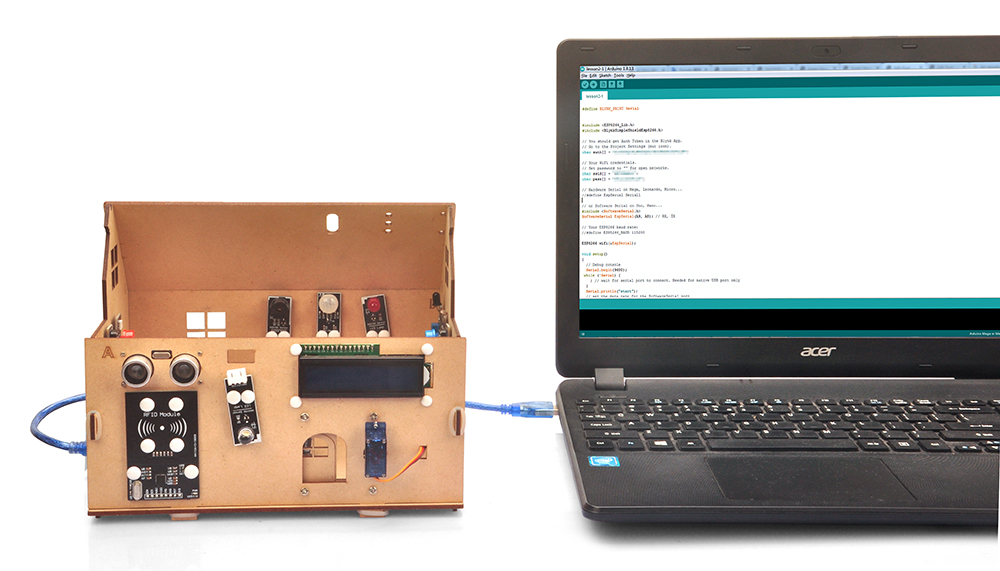
Step 2: Connect the OSOYOO MEGA2560 board to your PC with a USB cable.
Notice: Disconnect the battery or power adapter before uploading the sketch to the Arduino.
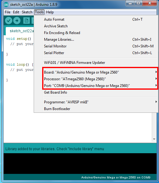
Step 6: Open Arduino IDE. Select the correct board type and port for your project.
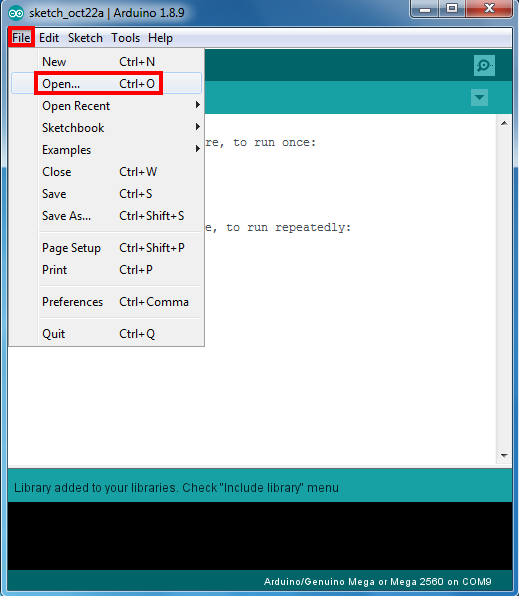
Step 7: In Arduino IDE, click File → Open, select the sketch file from the unzipped folder, then upload it to your Arduino.
Note: In the sketch, find line 13 as shown below:
char auth[] =”sM1i_rSJjDlQxesfuhOzrL0h9NiivJkn”;
Replace sM1i_rSJjDlQxesfuhOzrL0h9NiivJkn with your own Blynk token. If you do not know how to get a token, read this article.
Then find lines 22–24 and replace the Wi-Fi SSID, password, and Blynk server IP address:
char ssid[] = "***";//replace with your Wi-Fi SSID
char pass[] = "***"; //replace with your Wi-Fi password
char server_ip[]="192.168.1.81"; // replace with your Blynk server IP address

Upload the sketch to the board. Wait until you see:
Done uploading
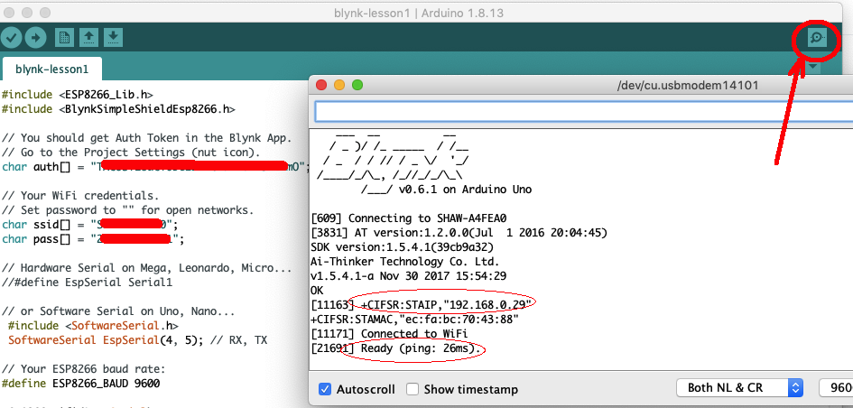
Open the Serial Monitor (upper right corner). You should see your Arduino’s IP address and a Ready message, as shown below:
Congratulations! Your hardware is now connected to the Blynk cloud!
If you cannot see an IP address, check your Wi-Fi SSID and password in the code. If you see the IP address but no Ready message, verify that your Blynk token and local server IP address are correctly set in the code.
Blynk (Legacy) App Project Setup
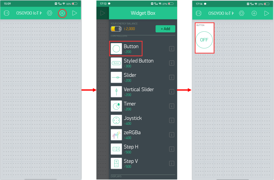
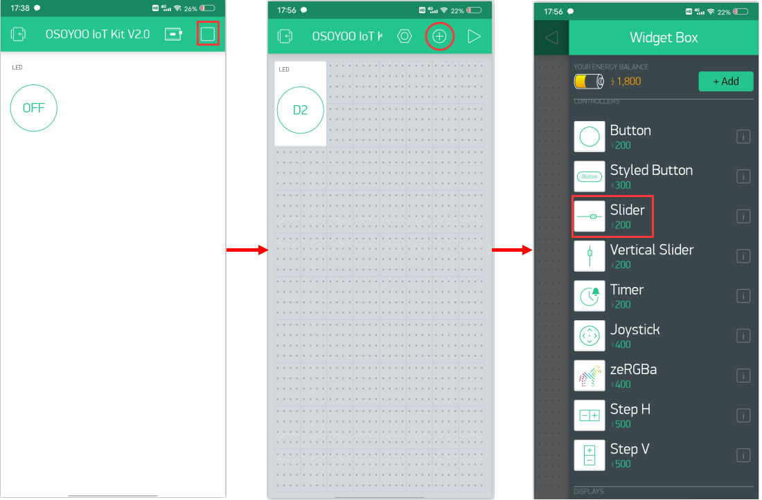
Open your project page and tap the “+” button to add a “Button” widget.
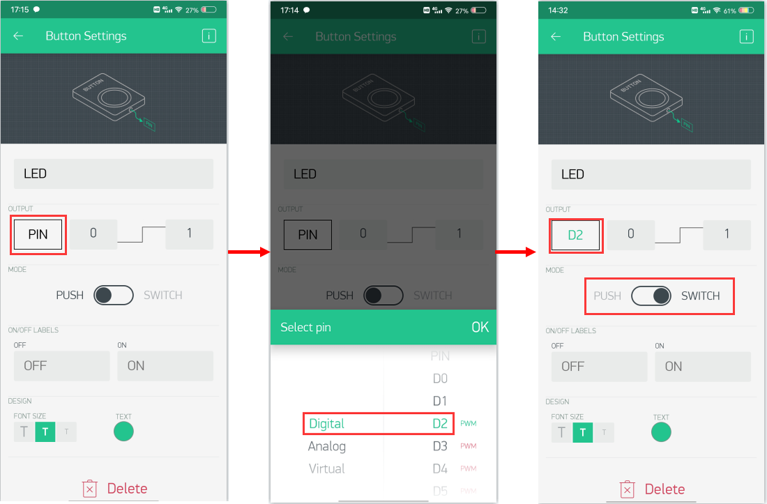
Button widget settings:
Name: You can name your button widget anything you like.
Output: D2 | 0–1
Mode: Select Switch mode.
You can adjust the other options to your preference or leave them as default.
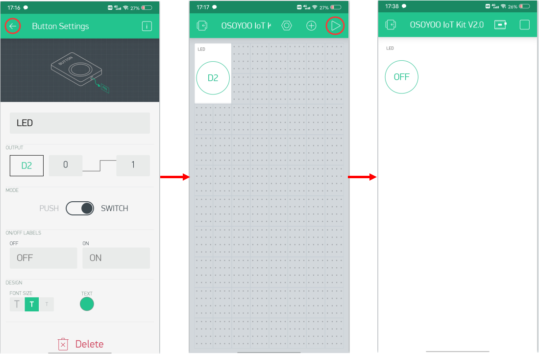
Then go back to the project page and tap the “▷” button to start your project.
Tap the Button on the project page and the LED connected to D2 will turn on.
Tap the Button again, and the LED will turn off.
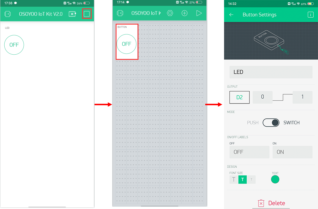
In PLAY mode, you cannot drag or add new widgets. Tap “□” to return to EDIT mode.
If the device appears offline, check your code, wiring, and app settings, then try again.
Remotely Control LED Brightness
In this section, we will show how to control the LED brightness using the kit and the Blynk app.
The wiring and code are the same as before. You only need to add a new widget.
App Project Setup
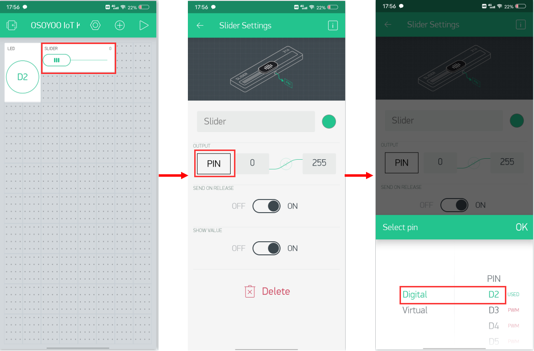
Open your project page and tap the “+” button to add a “Slider” widget.
Slider widget settings:
Name: You can name your slider widget anything you like.
Output: D2 | 0–255
You can adjust the other options to your preference or leave them as default.
Running Result
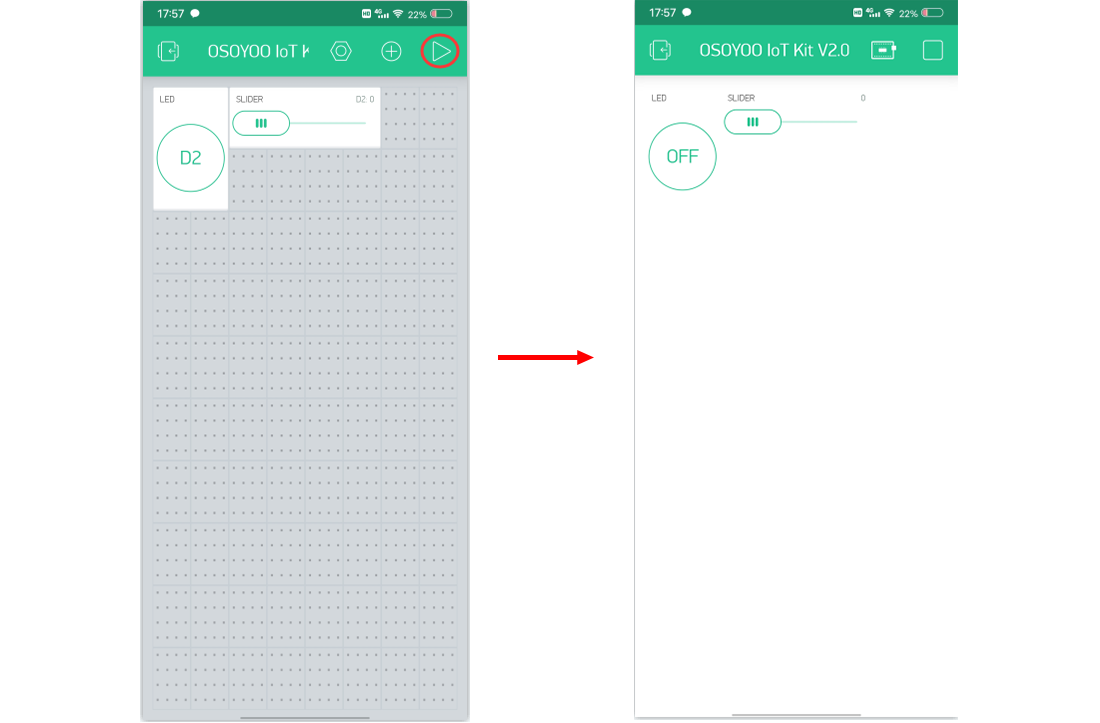
After completing all the steps above, open the Serial Monitor to verify the connection, then open the Blynk app and tap the PLAY button “▷” to switch from EDIT mode to PLAY mode and interact with the hardware.
In PLAY mode, you cannot drag or add new widgets. Tap “□” to return to EDIT mode.
Slide the slider to change the LED brightness. When the slider is at the far left, the LED is off; at the far right, it is at full brightness.
If the device appears offline, check your code, wiring, and app settings, then try again.
Hi Gabi,
1)Please put the two jumper caps to join A9 to ESP_TX , A8 to ESP_RX.
2)Make sure the Every Pin of the Wifi Shield is properly inserted into the MEGA2560 board.Sometimes, if some of the pins of wifi shield are not properly inserted into the MEGA2560, the wifi won’t work.
more detail seting about 1),2),please look at above tutorial at part “How to make”
3)Make sure you have compiled and uploaded the sketch to Arduino IDE properly(IDE must show Done upload!). If there is any error message when
you upload the sketch, please let us know.
After 1),2),3) is completed , your Serial monitor should show the ESP8266 connected to Wifi with IP address.
If still no update, please send email to [email protected] or [email protected].
Best Regards
Susan@OSOYOO support team





















Hello,
When I try to connect the ESP to the Wi-Fi I get the following result: [1715] ESP is not responding.
How can I connect it successfully?
Waiting for an answer from you.
Hi Gabi,
1)Please put the two jumper caps to join A9 to ESP_TX , A8 to ESP_RX.
2)Make sure the Every Pin of the Wifi Shield is properly inserted into the MEGA2560 board.Sometimes, if some of the pins of wifi shield are not properly inserted into the MEGA2560, the wifi won’t work.
more detail seting about 1),2),please look at above tutorial at part “How to make”
3)Make sure you have compiled and uploaded the sketch to Arduino IDE properly(IDE must show Done upload!). If there is any error message when
you upload the sketch, please let us know.
After 1),2),3) is completed , your Serial monitor should show the ESP8266 connected to Wifi with IP address.
If still no update, please send email to [email protected] or [email protected].
Best Regards
Susan@OSOYOO support team
Hi Susan,
the 2 jumper caps are well put, all the pins of the card are connected and there is no error on the code but it still does not work.
Best regards
Gabi